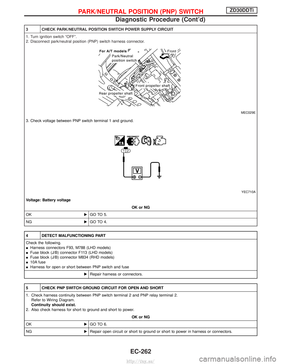
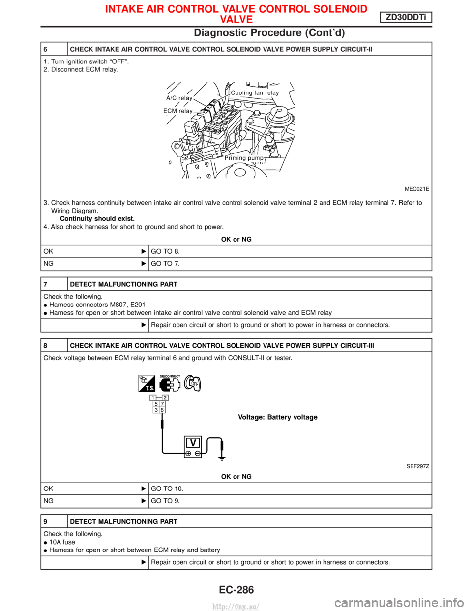
Page 525 of 1833
10 CHECK GLOW RELAY POWER SUPPLY CIRCUIT
1. Turn ignition switch ªOFFº.
2. Disconnect glow relay.
MEC004E
3. Check voltage between glow relay terminals 2, 5 and ground with CONSULT-II or tester.
YEC709AVoltage: Battery voltageOK or NG
OK EGO TO 12.
NG EGO TO 11.
11 DETECT MALFUNCTIONING PART
Check the following.
I80A fusible link
I 10A fuse
I Harness for open or short between glow relay and battery
ERepair harness or connectors.
12 CHECK GLOW RELAY OUTPUT SIGNAL CIRCUIT FOR OPEN AND SHORT
1. Disconnect ECM harness connector.
2. Check harness continuity between ECM terminal 111 and glow relay terminal 1. Refer to Wiring Diagram.
Continuity should exist.
3. Also check harness for short to ground and short to power.
OK or NG
OK EGO TO 14.
NG EGO TO 13.
GLOW CONTROL SYSTEMZD30DDTi
Diagnostic Procedure (Cont'd)
EC-250
http://vnx.su/
Page 537 of 1833

3 CHECK PARK/NEUTRAL POSITION SWITCH POWER SUPPLY CIRCUIT
1. Turn ignition switch ªOFFº.
2. Disconnect park/neutral position (PNP) switch harness connector.
MEC029E
3. Check voltage between PNP switch terminal 1 and ground.
YEC710A
Voltage: Battery voltageOK or NG
OK EGO TO 5.
NG EGO TO 4.
4 DETECT MALFUNCTIONING PART
Check the following.
IHarness connectors F93, M788 (LHD models)
I Fuse block (J/B) connector F113 (LHD models)
I Fuse block (J/B) connector M834 (RHD models)
I 10A fuse
I Harness for open or short between PNP switch and fuse
ERepair harness or connectors.
5 CHECK PNP SWITCH GROUND CIRCUIT FOR OPEN AND SHORT
1. Check harness continuity between PNP switch terminal 2 and PNP relay terminal 2.
Refer to Wiring Diagram.
Continuity should exist.
2. Also check harness for short to ground and short to power.
OK or NG
OK EGO TO 6.
NG ERepair open circuit or short to ground or short to power in harness or connectors.
PARK/NEUTRAL POSITION (PNP) SWITCHZD30DDTi
Diagnostic Procedure (Cont'd)
EC-262
http://vnx.su/
Page 543 of 1833

4 CHECK OVERALL FUNCTION-II
Check heat up switch indicator in the heat up switch under the following conditions.
MTBL1846
OK or NG
OK EINSPECTION END
NG EGO TO 9.
5 CHECK HEAT UP SWITCH POWER SUPPLY CIRCUIT
1. Turn heat up switch ªOFFº.
2. Turn ignition switch ªOFFº.
3. Disconnect heat up switch harness connector.
4. Turn ignition switch ªONº.
5. Check voltage between heat up switch terminal 2 and ground with CONSULT-II or tester.
MEC983DVoltage: Battery voltage
OK or NG
OK EGO TO 7.
NG EGO TO 6.
6 DETECT MALFUNCTIONING PART
Check the following.
IFuse block (J/B) connector F48
I 10A fuse
I Harness for open or short between heat up switch and fuse
ERepair open circuit or short to ground or short to power in harness or connectors.
7 CHECK HEAT UP SWITCH INPUT SIGNAL CIRCUIT FOR OPEN AND SHORT
1. Turn ignition switch ªOFFº.
2. Disconnect ECM harness connector.
3. Check harness continuity between ECM terminal 59 and heat up switch terminal 1. Refer to Wiring Diagram.
Continuity should exist.
4. Also check harness for short to ground and short to power.
OK or NG
OK EGO TO 7.
NG ERepair open circuit or short to ground or short to power in harness or connectors.
HEAT UP SWITCHZD30DDTi
Diagnostic Procedure (Cont'd)
EC-268
http://vnx.su/
Page 554 of 1833

8 CHECK SWIRL CONTROL VALVE CONTROL SOLENOID VALVE POWER SUPPLY CIRCUIT
1. Turn ignition switch ªOFFº.
2. Disconnect swirl control valve control solenoid valve harness connector.
MEC006E
3. Turn ignition switch ªONº.
4. Check voltage between swirl control valve control solenoid valve terminal 2 and ground with CONSULT-II or tester.
SEF312Z
OK or NG
OK EGO TO 10.
NG EGO TO 9.
9 DETECT MALFUNCTIONING PART
Check the following.
IHarness connectors F108, E225
I Harness connectors M842, F135
I Fuse block (J/B) connector F48 (LHD models), M756 (RHD models)
I 10A fuse
I Harness for open or short between swirl control valve control solenoid valve and fuse
ERepair open circuit or short to ground or short to power in harness or connectors.
10 CHECK SWIRL CONTROL VALVE CONTROL SOLENOID VALVE OUTPUT SIGNAL CIRCUIT FOR OPEN OR SHORT
1. Turn ignition switch ªOFFº.
2. Disconnect ECM harness connector.
3. Check harness continuity between ECM terminal 54 and swirl control valve control solenoid valve terminal 1. Refer to Wiring
Diagram. Continuity should exist.
4. Also check harness for short to ground and short to power.
OK or NG
OK EGO TO 12.
NG EGO TO 11.
SWIRL CONTROL VALVE CONTROL SOLENOID VALVEZD30DDTi
Diagnostic Procedure (Cont'd)
EC-279
http://vnx.su/
Page 561 of 1833

6 CHECK INTAKE AIR CONTROL VALVE CONTROL SOLENOID VALVE POWER SUPPLY CIRCUIT-II
1. Turn ignition switch ªOFFº.
2. Disconnect ECM relay.
MEC021E
3. Check harness continuity between intake air control valve control solenoid valve terminal 2 and ECM relay terminal 7. Refer toWiring Diagram. Continuity should exist.
4. Also check harness for short to ground and short to power.
OK or NG
OK EGO TO 8.
NG EGO TO 7.
7 DETECT MALFUNCTIONING PART
Check the following.
IHarness connectors M807, E201
I Harness for open or short between intake air control valve control solenoid valve and ECM relay
ERepair open circuit or short to ground or short to power in harness or connectors.
8 CHECK INTAKE AIR CONTROL VALVE CONTROL SOLENOID VALVE POWER SUPPLY CIRCUIT-III
Check voltage between ECM relay terminal 6 and ground with CONSULT-II or tester.
SEF297Z
OK or NG
OK EGO TO 10.
NG EGO TO 9.
9 DETECT MALFUNCTIONING PART
Check the following.
I10A fuse
I Harness for open or short between ECM relay and battery
ERepair open circuit or short to ground or short to power in harness or connectors.
INTAKE AIR CONTROL VALVE CONTROL SOLENOID
VA LV EZD30DDTi
Diagnostic Procedure (Cont'd)
EC-286
http://vnx.su/
Page 570 of 1833

7 DETECT MALFUNCTIONING PART
Check the following.
IHarness connectors M842, F135 (RHD models)
I Fuse block (J/B) connector F48 (LHD models), M756 (RHD models)
I 10A fuse
I Harness for open or short between variable nozzle turbocharger control solenoid valve and fuse
ERepair open circuit or short to ground or short to power in harness or connectors.
8 CHECK VARIABLE NOZZLE TURBOCHARGER CONTROL SOLENOID VALVE OUTPUT SIGNAL CIRCUIT FOR
OPEN OR SHORT
1. Turn ignition switch ªOFFº.
2. Disconnect ECM harness connector.
3. Check harness continuity between ECM terminal 101 and variable nozzle turbocharger control solenoid valve terminal 1. Refer to Wiring Diagram. Continuity should exist.
4. Also check harness for short to ground and short to power.
OK or NG
OK EGO TO 10.
NG EGO TO 9.
9 DETECT MALFUNCTIONING PART
Check the following.
IHarness connectors F135, M842 (RHD models)
I Harness for open or short between variable nozzle turbocharger control solenoid valve and ECM
ERepair open circuit or short to ground or short to power in harness or connectors.
VARIABLE NOZZLE TURBOCHARGER CONTROL
SOLENOID VALVEZD30DDTi
Diagnostic Procedure (Cont'd)
EC-295
http://vnx.su/
Page 578 of 1833

9 DETECT MALFUNCTIONING PART
Check the following.
I10A fuse
I Fuse block (J/B) connector F48 (LHD models)
I Fuse block (J/B) connector M756 (RHD models)
I Harness for open or short between combination meter and fuse block
ERepair open circuit or short to ground or short to power in harness or connectors.
10 CHECK ENGINE OIL PRESSURE SWITCH-1 INPUT SIGNAL CIRCUIT
1. Turn ignition switch ªOFFº.
2. Disconnect engine oil pressure switch-1 harness connector.
3. Check harness continuity between combination meter terminal 16 and engine oil pressure switch-1 terminal 1.
Refer to Wiring Diagram.
Continuity should exist.
4. Also check harness for short to power.
OK or NG
OK EGO TO 12.
NG EGO TO 11.
11 DETECT MALFUNCTIONING PART
Check the following.
IHarness connectors F108, E225
I Harness connectors M842, F135 (RHD models)
I Harness for open or short between combination meter and engine oil pressure switch-1
ERepair open circuit or short to power in harness or connectors.
ENGINE OIL PRESSURE SWITCHZD30DDTi
Diagnostic Procedure (Cont'd)
EC-303
http://vnx.su/
Page 581 of 1833
19 CHECK ENGINE OIL PRESSURE SWITCH-2 INPUT SIGNAL CIRCUIT
1. Turn ignition switch ªOFFº.
2. Disconnect engine oil pressure switch-2 harness connector.
3. Turn ignition switch ªONº.
4. Check voltage between engine oil pressure switch-2 terminal 1 and ground with CONSULT-II or tester.
SEC976D
Voltage: Battery voltageOK or NG
OK EGO TO 21.
NG EGO TO 20.
20 DETECT MALFUNCTIONING PART
Check the following.
IHarness connectors M807, E201
I Harness connectors F120, M812 (LHD models)
I Resistor
I 10A fuse
I Fuse block (J/B) connector F48 (LHD models)
I Fuse block (J/B) connector M756 (RHD models)
I Harness for open between engine oil pressure switch-2 and fuse
ERepair harness or connectors.
21 CHECK ECM INPUT SIGNAL CIRCUIT-I
Check voltage between ECM terminal 27 and ground with CONSULT-II or tester.
SEC388DVoltage: Battery voltage
OK or NG
OK EGO TO 23.
NG EGO TO 22.
ENGINE OIL PRESSURE SWITCHZD30DDTi
Diagnostic Procedure (Cont'd)
EC-306
http://vnx.su/