Page 1246 of 1833
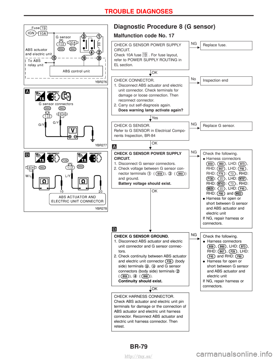
Diagnostic Procedure 8 (G sensor)
Malfunction code No. 17
CHECK G SENSOR POWER SUPPLY
CIRCUIT.
Check 10A fuse
19. For fuse layout,
refer to POWER SUPPLY ROUTING in
EL section.
OK
ENG Replace fuse.
CHECK CONNECTOR.
1. Disconnect ABS actuator and electric
unit connector. Check terminals for
damage or loose connection. Then
reconnect connector.
2. Carry out self-diagnosis again. Does warning lamp activate again?
Ye s
ENo Inspection end
CHECK G SENSOR.
Refer to G SENSOR in Electrical Compo-
nents Inspection, BR-84
OK
ENGReplace G sensor.
CHECK G SENSOR POWER SUPPLY
CIRCUIT.
1. Disconnect G sensor connectors.
2. Check voltage between G sensor con- nector terminals q
1(B59),q3(B60)
and ground.
Battery voltage should exist.
OK
ENG Check the following.
IHarness connectors
B59,B60, LHD:B73,
RHD:
B67, LHD:F66,
RHD:
F76:, RHD:
F136:, LHD:M787,
RHD:
M743:, RHD:
M829:, LHD:F45,
RHD:
F80andM822
I Harness for open or
short between G sensor
and ABS actuator and
electric unit
If NG, repair harness or
connectors.
CHECK G SENSOR GROUND.
1. Disconnect ABS actuator and electric unit connector and G sensor connec-
tors.
2. Check continuity between ABS actuator and electric unit connector
F29(body
side) terminals q
20,q10and G sensor
connectors (body side) terminals q
2
(B59),q4(B60).
Continuity should exist.
OK
ENG Check the following.
IHarness connectors
B59,B60, LHD:B73,
RHD:
B67,F29, LHD:
F45and RHD:F80
I Harness for open or
short between G sensor
and ABS actuator and
electric unit
If NG, repair harness or
connectors.
CHECK HARNESS CONNECTOR.
Check ABS actuator and electric unit pin
terminals for damage or the connection of
ABS actuator and electric unit harness
connector. Reconnect ABS actuator and
electric unit harness connector. Then
retest.
YBR276
YBR277
YBR278
H
H
H
H
H
TROUBLE DIAGNOSES
BR-79
http://vnx.su/
Page 1306 of 1833
How to Perform Trouble Diagnoses for Quick
and Accurate Repair
A good understanding of the malfunction conditions can make troubleshooting faster and more accurate.
In general, each customer feels differently about a malfunction. It is important to fully understand the symp-
toms or conditions for a customer complaint.
INFORMATION FROM CUSTOMER
WHAT ..... Vehicle model
WHEN ..... Date, Frequencies
WHERE ..... Road conditions
HOW ..... Operating conditions, Symptoms
PRELIMINARY CHECK
Check that the following parts are in good order.
IBattery [Refer to SC-3, ªBATTERYº.]
I Fuse [Refer to EL-12, ªFuseº, ªPOWER SUPPLY ROUTINGº.]
I System component-to-harness connections
SUPPLEMENTAL RESTRAINT SYSTEM (SRS)
RS-31
http://vnx.su/
Page 1313 of 1833
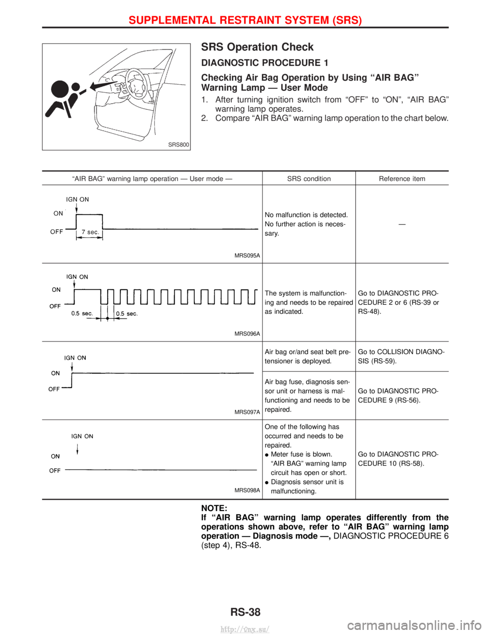
SRS Operation Check
DIAGNOSTIC PROCEDURE 1
Checking Air Bag Operation by Using ªAIR BAGº
Warning Lamp Ð User Mode
1. After turning ignition switch from ªOFFº to ªONº, ªAIR BAGºwarning lamp operates.
2. Compare ªAIR BAGº warning lamp operation to the chart below.
ªAIR BAGº warning lamp operation Ð User mode Ð SRS conditionReference item
MRS095A
No malfunction is detected.
No further action is neces-
sary. Ð
MRS096A
The system is malfunction-
ing and needs to be repaired
as indicated.Go to DIAGNOSTIC PRO-
CEDURE 2 or 6 (RS-39 or
RS-48).
MRS097A
Air bag or/and seat belt pre-
tensioner is deployed.
Go to COLLISION DIAGNO-
SIS (RS-59).
Air bag fuse, diagnosis sen-
sor unit or harness is mal-
functioning and needs to be
repaired. Go to DIAGNOSTIC PRO-
CEDURE 9 (RS-56).
MRS098A
One of the following has
occurred and needs to be
repaired.
I
Meter fuse is blown.
ªAIR BAGº warning lamp
circuit has open or short.
I Diagnosis sensor unit is
malfunctioning. Go to DIAGNOSTIC PRO-
CEDURE 10 (RS-58).
NOTE:
If ªAIR BAGº warning lamp operates differently from the
operations shown above, refer to ªAIR BAGº warning lamp
operation Ð Diagnosis mode Ð,
DIAGNOSTIC PROCEDURE 6
(step 4), RS-48.
SRS800
SUPPLEMENTAL RESTRAINT SYSTEM (SRS)
RS-38
http://vnx.su/
Page 1330 of 1833
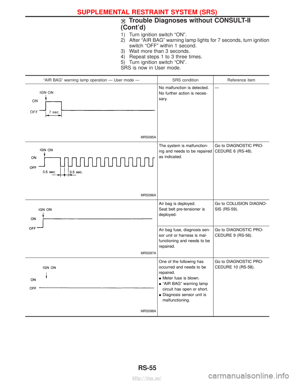
1) Turn ignition switch ªONº.
2) After ªAIR BAGº warning lamp lights for 7 seconds, turn ignitionswitch ªOFFº within 1 second.
3) Wait more than 3 seconds.
4) Repeat steps 1 to 3 three times.
5) Turn ignition switch ªONº.
SRS is now in User mode.
ªAIR BAGº warning lamp operation Ð User mode Ð SRS conditionReference item
MRS095A
No malfunction is detected.
No further action is neces-
sary. Ð
MRS096A
The system is malfunction-
ing and needs to be repaired
as indicated.Go to DIAGNOSTIC PRO-
CEDURE 6 (RS-48).
MRS097A
Air bag is deployed.
Seat belt pre-tensioner is
deployed.Go to COLLISION DIAGNO-
SIS (RS-59).
Air bag fuse, diagnosis sen-
sor unit or harness is mal-
functioning and needs to be
repaired. Go to DIAGNOSTIC PRO-
CEDURE 9 (RS-56).
MRS098A
One of the following has
occurred and needs to be
repaired.
I
Meter fuse is blown.
I ªAIR BAGº warning lamp
circuit has open or short.
I Diagnosis sensor unit is
malfunctioning. Go to DIAGNOSTIC PRO-
CEDURE 10 (RS-58).
SUPPLEMENTAL RESTRAINT SYSTEM (SRS)
Trouble Diagnoses without CONSULT-II
(Cont'd)
RS-55
http://vnx.su/
Page 1331 of 1833
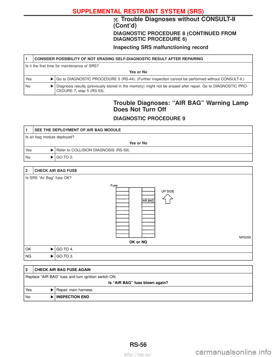
DIAGNOSTIC PROCEDURE 8 (CONTINUED FROM
DIAGNOSTIC PROCEDURE 6)
Inspecting SRS malfunctioning record
1 CONSIDER POSSIBILITY OF NOT ERASING SELF-DIAGNOSTIC RESULT AFTER REPAIRING
Is it the first time for maintenance of SRS?YesorNo
Ye s EGo to DIAGNOSTIC PROCEDURE 5 (RS-44). (Further inspection cannot be performed without CONSULT-II.)
No EDiagnosis results (previously stored in the memory) might not be erased after repair. Go to DIAGNOSTIC PRO-
CEDURE 7, step 5 (RS-53).
Trouble Diagnoses: ªAIR BAGº Warning Lamp
Does Not Turn Off
DIAGNOSTIC PROCEDURE 9
1 SEE THE DEPLOYMENT OF AIR BAG MODULE
Is air bag module deployed?
YesorNo
Ye s ERefer to COLLISION DIAGNOSIS (RS-59).
No EGO TO 2.
2 CHECK AIR BAG FUSE
Is SRS ªAir Bagº fuse OK?
NRS093
OK or NG
OK EGO TO 4.
NG EGO TO 3.
3 CHECK AIR BAG FUSE AGAIN
Replace ªAIR BAGº fuse and turn ignition switch ON.
Is ªAIR BAGº fuse blown again?
Ye s ERepair main harness.
No EINSPECTION END
SUPPLEMENTAL RESTRAINT SYSTEM (SRS)
Trouble Diagnoses without CONSULT-II
(Cont'd)
RS-56
http://vnx.su/
Page 1333 of 1833
Trouble Diagnoses: ªAIR BAGº Warning Lamp
Does Not Turn On
DIAGNOSTIC PROCEDURE 10
1 CHECK ªMETERº FUSE
Is meter fuse OK?
NRS092
OK or NG
OK EGO TO 3.
NG EGO TO 2.
2 CHECK ªMETERº FUSE AGAIN
Replace meter fuse and turn ignition switch ON.
Is meter fuse blown again?
Ye s ERepair main harness.
No EINSPECTION END
3 CHECK ªAIR BAGº WARNING LAMP LED
Is ªAIR BAGº warning lamp LED OK?
OK or NG
OK EGO TO 4.
NG EReplace ªAIR BAGº warning lamp LED.
4 CHECK HARNESS CONNECTION BETWEEN DIAGNOSIS SENSOR UNIT AND ªAIR BAGº WARNING LAMP
Disconnect diagnosis sensor unit connector and turn ignition switch ªONº.
IDoes ªAIR BAGº warning lamp turn on?
YesorNo
Ye s EReplace diagnosis sensor unit.
No ECheck the ground circuit of ªAIR BAGº warning lamp.
SUPPLEMENTAL RESTRAINT SYSTEM (SRS)
RS-58
http://vnx.su/
Page 1434 of 1833
Symptom Chart
DIAGNOSTIC TABLE
PROCEDUREPrelimi-
nary
Check Diagnostic
Procedure Main Power
Supply and
Ground Circuit Check Electrical Components Inspection
SYMPTOM
Preliminary check 1
Preliminary check 2
Diagnostic procedure 1
Diagnostic procedure 2
Diagnostic procedure 3
15A Fuses
10A Fuse
15A Fuse
Blower motor
Intake door motor
Resistor
A/C switch
Fan switch
A/C relay
Dual-pressure switch Compressor
Harness Magnet clutch
A/C does not blow cold air.q qqqq qqqqqqq
Blower motor does not rotate.
qqqqq q
Magnet clutch does not
engage when A/C switch and
fan switch are ON.
qq qqqqqq
Noise
Intake door does not change.qq q
,: The number indicates checking order.
q: Refer to each flow chart for checking order. (It depends on malfunctioning portion.)
TROUBLE DIAGNOSES
HA-37
http://vnx.su/
Page 1450 of 1833
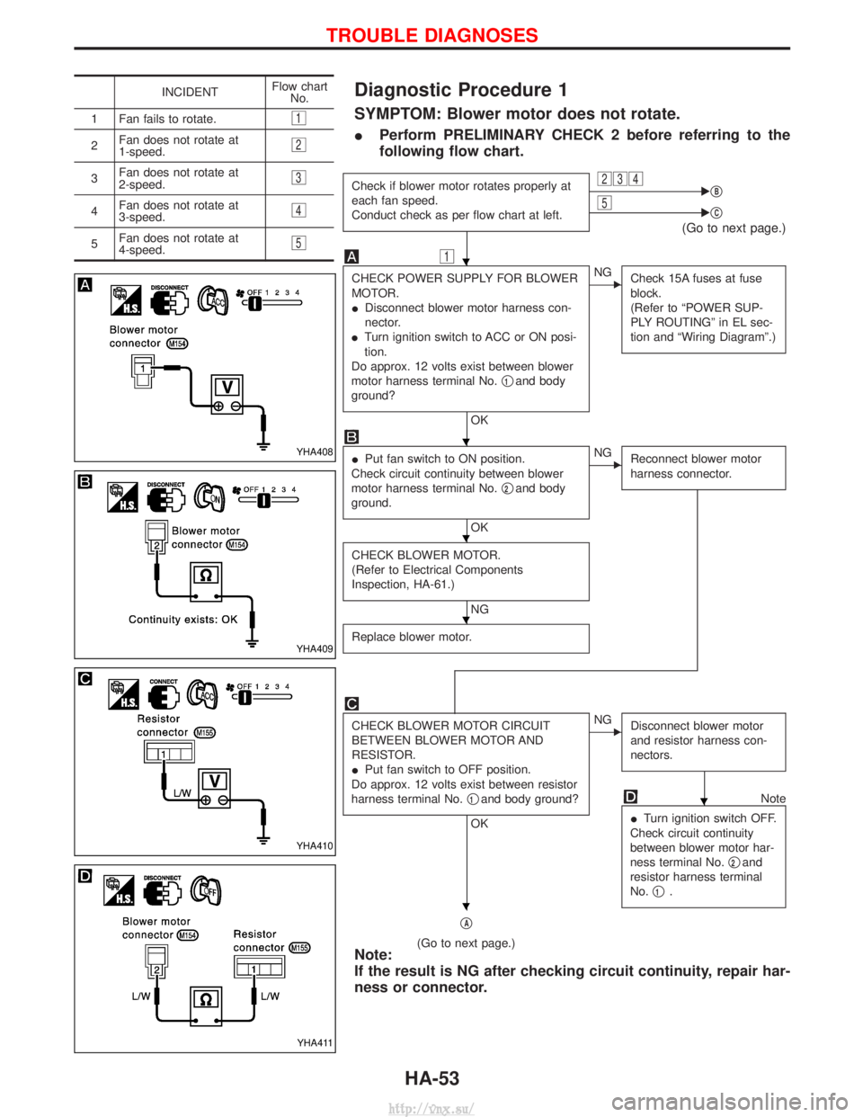
Diagnostic Procedure 1
SYMPTOM: Blower motor does not rotate.
IPerform PRELIMINARY CHECK 2 before referring to the
following flow chart.
Check if blower motor rotates properly at
each fan speed.
Conduct check as per flow chart at left.234EqB5EqC
(Go to next page.)
1
CHECK POWER SUPPLY FOR BLOWER
MOTOR.
I
Disconnect blower motor harness con-
nector.
I Turn ignition switch to ACC or ON posi-
tion.
Do approx. 12 volts exist between blower
motor harness terminal No. q
1and body
ground?
OK
ENG Check 15A fuses at fuse
block.
(Refer to ªPOWER SUP-
PLY ROUTINGº in EL sec-
tion and ªWiring Diagramº.)
IPut fan switch to ON position.
Check circuit continuity between blower
motor harness terminal No. q
2and body
ground.
OK
ENG Reconnect blower motor
harness connector.
CHECK BLOWER MOTOR.
(Refer to Electrical Components
Inspection, HA-61.)
NG
Replace blower motor.
CHECK BLOWER MOTOR CIRCUIT
BETWEEN BLOWER MOTOR AND
RESISTOR.
I Put fan switch to OFF position.
Do approx. 12 volts exist between resistor
harness terminal No. q
1and body ground?
OK
ENG
Disconnect blower motor
and resistor harness con-
nectors.
Note
I Turn ignition switch OFF.
Check circuit continuity
between blower motor har-
ness terminal No. q
2and
resistor harness terminal
No. q
1.
qA
(Go to next page.)Note:
If the result is NG after checking circuit continuity, repair har-
ness or connector.
INCIDENT Flow chart
No.
1 Fan fails to rotate.
1
2 Fan does not rotate at
1-speed.2
3Fan does not rotate at
2-speed.3
4Fan does not rotate at
3-speed.4
5Fan does not rotate at
4-speed.5
YHA408
YHA409
YHA410
YHA411
H
H
H
H
H
H
TROUBLE DIAGNOSES
HA-53
http://vnx.su/