Page 1572 of 1833
DRIVER SIDE DOOR SWITCH CHECK
CHECK DOOR SWITCH INPUT SIGNAL.
Check voltage between fuse block (J/B)
and ground.
NG
EOKDoor switch is OK.
CHECK DOOR SWITCH.
1. Disconnect door switch connector.
2. Check continuity between door switch terminal 1 and ground.
OK
ENG Replace door switch.
Check the following.
IDoor switch case ground condition
I Harness for open or short between con-
trol unit and door switch
Termi-
nals Condition Voltage (V)
Driver
side door
B07Opened 0 Closed Approx. 12
Terminals Condition Continuity
Door
switch q
1-
ground Closed No
Open Yes
YEL874E
YEL875E
H
H
INTERIOR LAMP
Trouble Diagnoses (Cont'd)
EL-79
http://vnx.su/
Page 1574 of 1833
OTHER DOOR SWITCH CHECK
CHECK DOOR SWITCH INPUT SIGNAL.
Check voltage between fuse block (J/B)
and ground.
NG
EOKDoor switch is OK.
CHECK DOOR SWITCH.
1. Disconnect door switch connector.
2. Check continuity between door switch terminals.
OK
ENG Replace door switch.
Check the following.
IDoor switch ground condition
I Harness for open or short between con-
trol unit and door switch
Termi-
nals Condition Voltage (V)
Other
door
B01Opened 0 Closed Approx. 12
Terminals Condition Continuity
Other
door
switches q
1-
ground Closed No
Open Yes
YEL878E
YEL879E
H
H
INTERIOR LAMP
Trouble Diagnoses (Cont'd)
EL-81
http://vnx.su/
Page 1576 of 1833
![NISSAN TERRANO 2004 Service Repair Manual POWER SUPPLY AND GROUND CIRCUIT
Power is supplied at all times
Ithrough 10A fuse [No. 16, located in the fuse block (J/B)]
I to combination meter terminal 27.
With the ignition switch in the ON or STA NISSAN TERRANO 2004 Service Repair Manual POWER SUPPLY AND GROUND CIRCUIT
Power is supplied at all times
Ithrough 10A fuse [No. 16, located in the fuse block (J/B)]
I to combination meter terminal 27.
With the ignition switch in the ON or STA](/manual-img/5/57394/w960_57394-1575.png)
POWER SUPPLY AND GROUND CIRCUIT
Power is supplied at all times
Ithrough 10A fuse [No. 16, located in the fuse block (J/B)]
I to combination meter terminal 27.
With the ignition switch in the ON or START position, power is supplied
I through 10A fuse [No. 12, located in the fuse block (J/B)]
I to combination meter terminal 28.
Ground is supplied
I through body grounds F36, F47 (LHD models) or M33, M754 (RHD models)
I to combination meter terminal 29.
WATER TEMPERATURE GAUGE
The water temperature gauge indicates the engine coolant temperature.
Thermal transmitter provides a engine coolant temperature signal to combination meter for water temperature
gauge.
TACHOMETER
The tachometer indicates engine speed in revolution per minutes (rpm). ECM provides an engine speed sig-
nal to combination meter for tachometer.
FUEL GAUGE
The fuel gauge indicates the approximate fuel level in the fuel tank.
The fuel gauge is regulated by a variable ground signal supplied
Ifrom body grounds B10 and B18
I through terminal 3 of the fuel level sensor unit and
I through terminal 2 (TD27Ti engine) or 1 (ZD30DDTi engine) of the fuel level sensor unit
I to combination meter terminal 13 for the fuel gauge.
SPEEDOMETER
The combination meter receives a signal from vehicle speed sensor. The speedometer converts the signal into
the vehicle speed displayed.
AMBIENT TEMPERATURE GAUGE
Ambient temperature sensor provides the signal for ambient temperature to combination meter.
METER AND GAUGES
System Description (Cont'd)
EL-83
http://vnx.su/
Page 1587 of 1833
POWER SUPPLY AND GROUND CIRCUIT CHECK
Power Supply Circuit Check
TerminalsIgnition switch position
(+) (-) OFF ACC ON
27 Ground Battery volt-
age Battery volt-
age Battery volt-
age
28 Ground 0V 0V Battery volt-
age
If NG, check the following.
I10A fuse [No. 12, located in fuse block (J/B)]
I 10A fuse [No. 16, located in fuse block (J/B)]
I Harness for open or short between fuse and combination meter
Ground Circuit Check
Terminals Continuity
29 - Ground Yes
YEL885E
YEL886E
METER AND GAUGES
Trouble Diagnoses (Cont'd)
EL-94
http://vnx.su/
Page 1588 of 1833

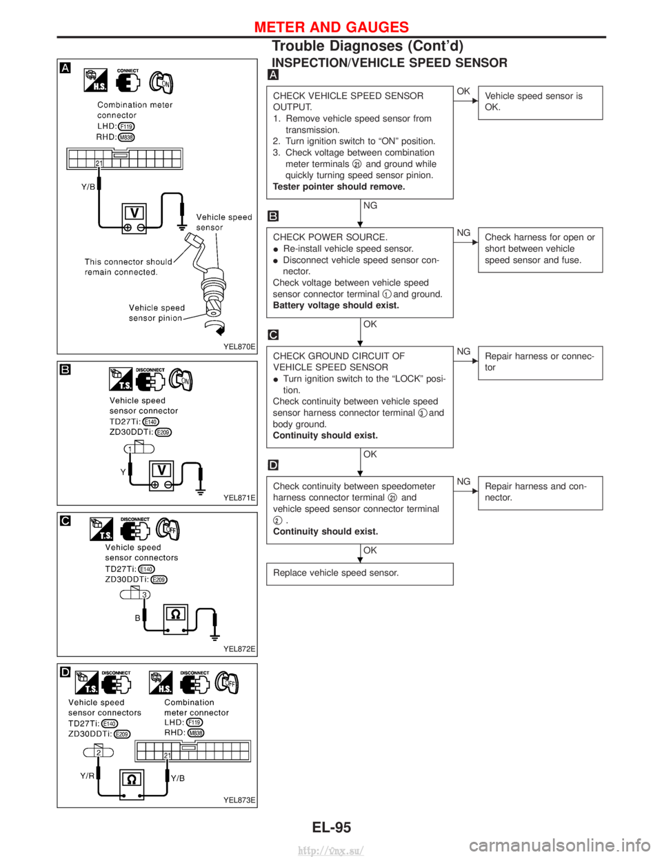
INSPECTION/VEHICLE SPEED SENSOR
CHECK VEHICLE SPEED SENSOR
OUTPUT.
1. Remove vehicle speed sensor fromtransmission.
2. Turn ignition switch to ªONº position.
3. Check voltage between combination meter terminals q
21and ground while
quickly turning speed sensor pinion.
Tester pointer should remove.
NG
EOK Vehicle speed sensor is
OK.
CHECK POWER SOURCE.
IRe-install vehicle speed sensor.
I Disconnect vehicle speed sensor con-
nector.
Check voltage between vehicle speed
sensor connector terminal q
1and ground.
Battery voltage should exist.
OK
ENG Check harness for open or
short between vehicle
speed sensor and fuse.
CHECK GROUND CIRCUIT OF
VEHICLE SPEED SENSOR
ITurn ignition switch to the ªLOCKº posi-
tion.
Check continuity between vehicle speed
sensor harness connector terminal q
3and
body ground.
Continuity should exist.
OK
ENG Repair harness or connec-
tor
Check continuity between speedometer
harness connector terminal q
21and
vehicle speed sensor connector terminal
q
2.
Continuity should exist.
OK
ENG Repair harness and con-
nector.
Replace vehicle speed sensor.
YEL870E
YEL871E
YEL872E
YEL873E
H
H
H
H
METER AND GAUGES
Trouble Diagnoses (Cont'd)
EL-95
http://vnx.su/
Page 1618 of 1833

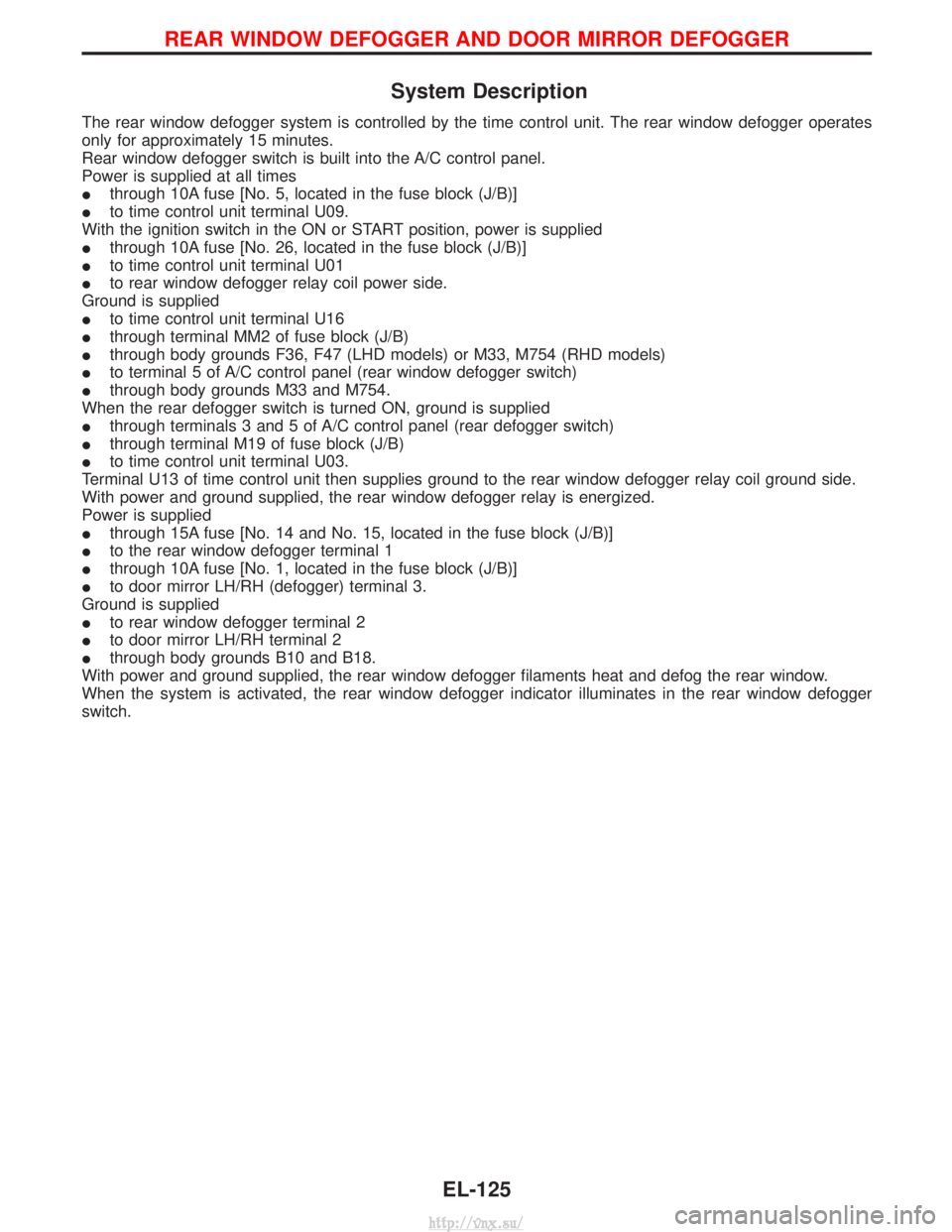
System Description
The rear window defogger system is controlled by the time control unit. The rear window defogger operates
only for approximately 15 minutes.
Rear window defogger switch is built into the A/C control panel.
Power is supplied at all times
Ithrough 10A fuse [No. 5, located in the fuse block (J/B)]
I to time control unit terminal U09.
With the ignition switch in the ON or START position, power is supplied
I through 10A fuse [No. 26, located in the fuse block (J/B)]
I to time control unit terminal U01
I to rear window defogger relay coil power side.
Ground is supplied
I to time control unit terminal U16
I through terminal MM2 of fuse block (J/B)
I through body grounds F36, F47 (LHD models) or M33, M754 (RHD models)
I to terminal 5 of A/C control panel (rear window defogger switch)
I through body grounds M33 and M754.
When the rear defogger switch is turned ON, ground is supplied
I through terminals 3 and 5 of A/C control panel (rear defogger switch)
I through terminal M19 of fuse block (J/B)
I to time control unit terminal U03.
Terminal U13 of time control unit then supplies ground to the rear window defogger relay coil ground side.
With power and ground supplied, the rear window defogger relay is energized.
Power is supplied
I through 15A fuse [No. 14 and No. 15, located in the fuse block (J/B)]
I to the rear window defogger terminal 1
I through 10A fuse [No. 1, located in the fuse block (J/B)]
I to door mirror LH/RH (defogger) terminal 3.
Ground is supplied
I to rear window defogger terminal 2
I to door mirror LH/RH terminal 2
I through body grounds B10 and B18.
With power and ground supplied, the rear window defogger filaments heat and defog the rear window.
When the system is activated, the rear window defogger indicator illuminates in the rear window defogger
switch.
REAR WINDOW DEFOGGER AND DOOR MIRROR DEFOGGER
EL-125
http://vnx.su/
Page 1621 of 1833

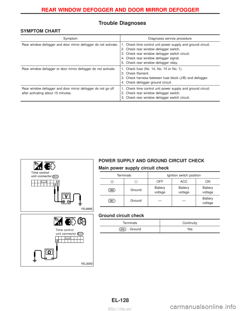
Trouble Diagnoses
SYMPTOM CHART
SymptomDiagnoses service procedure
Rear window defogger and door mirror defogger do not activate. 1. Check time control unit power supply and ground circuit. 2. Check rear window defogger switch.
3. Check rear window defogger switch circuit.
4. Check rear window defogger signal.
5. Check rear window defogger relay.
Rear window defogger or door mirror defogger do not activate. 1. Check fuse (No. 14, No. 15 or No. 1). 2. Check filament.
3. Check harness between fuse block (J/B) and defogger.
4. Check defogger ground circuit.
Rear window defogger and door mirror defogger do not go off
after activating about 15 minutes. 1. Check time control unit power supply and ground circuit.
2. Check rear window defogger switch.
3. Check rear window defogger switch circuit.
POWER SUPPLY AND GROUND CIRCUIT CHECK
Main power supply circuit check
Terminals
Ignition switch position
!@ OFF ACC ON
U09GroundBattery
voltage Battery
voltage Battery
voltage
U01Ground ÐÐBattery
voltage
Ground circuit check
Terminals Continuity
U16- GroundYes
YEL888E
YEL300D
REAR WINDOW DEFOGGER AND DOOR MIRROR DEFOGGER
EL-128
http://vnx.su/
Page 1622 of 1833

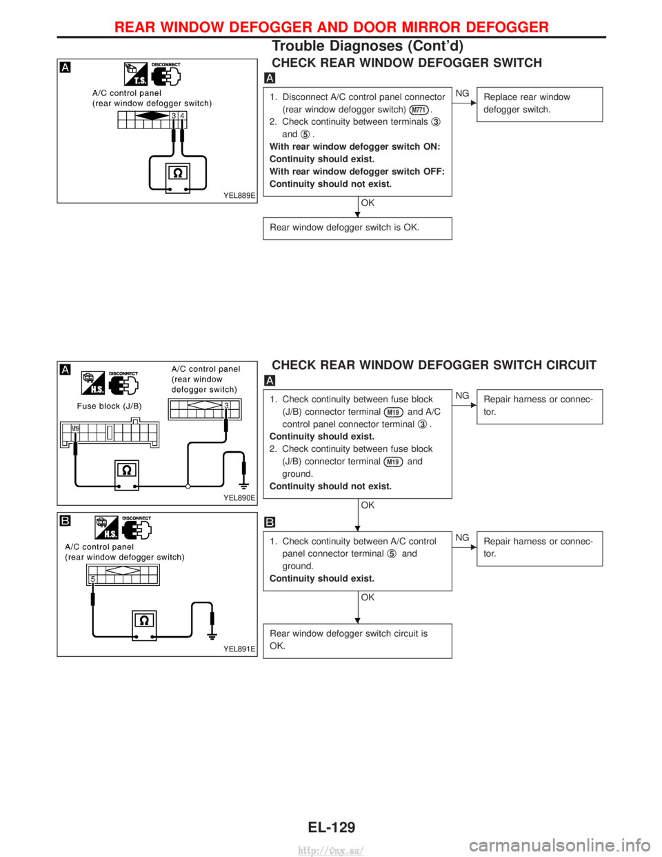
CHECK REAR WINDOW DEFOGGER SWITCH
1. Disconnect A/C control panel connector(rear window defogger switch)
M771.
2. Check continuity between terminals q
3
andq5.
With rear window defogger switch ON:
Continuity should exist.
With rear window defogger switch OFF:
Continuity should not exist.
OK
ENG Replace rear window
defogger switch.
Rear window defogger switch is OK.
CHECK REAR WINDOW DEFOGGER SWITCH CIRCUIT
1. Check continuity between fuse block
(J/B) connector terminal
M19and A/C
control panel connector terminal q
3.
Continuity should exist.
2. Check continuity between fuse block (J/B) connector terminal
M19and
ground.
Continuity should not exist.
OK
ENG Repair harness or connec-
tor.
1. Check continuity between A/C control
panel connector terminal q
5and
ground.
Continuity should exist.
OK
ENG Repair harness or connec-
tor.
Rear window defogger switch circuit is
OK.
YEL889E
YEL890E
YEL891E
H
H
H
REAR WINDOW DEFOGGER AND DOOR MIRROR DEFOGGER
Trouble Diagnoses (Cont'd)
EL-129
http://vnx.su/