2004 NISSAN TERRANO fuse
[x] Cancel search: fusePage 1515 of 1833
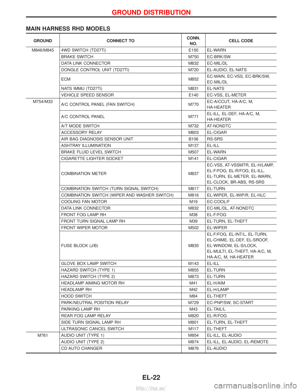
MAIN HARNESS RHD MODELS
GROUNDCONNECT TO CONN.
NO. CELL CODE
M846/M845 4WD SWITCH (TD27Ti) E150 EL-WARN
BRAKE SWITCH M750 EC-BRK/SW
DATA LINK CONNECTOR M832 EC-MIL/DL
DONGLE CONTROL UNIT (TD27Ti) M720 EL-AUDIO, EL-NATS
ECM M852EC-MAIN, EC-VSS, EC-BRK/SW,
EC-MIL/DL
NATS IMMU (TD27Ti) M831 EL-NATS
VEHICLE SPEED SENSOR E140 EC-VSS, EL-METER
M754/M33 A/C CONTROL PANEL (FAN SWITCH) M770EC-A/CCUT, HA-A/C, M,
HA-HEATER
A/C CONTROL PANEL M771EL-ILL, EL-DEF, HA-A/C, M,
HA-HEATER
A/T MODE SWITCH M732 AT-NONDTC
ACCESSORY RELAY M803 EL-CIGAR
AIR BAG DIAGNOSIS SENSOR UNIT B106 RS-SRS
ASHTRAY ILLUMINATION M137 EL-ILL
BRAKE FLUID LEVEL SWITCH M507 EL-WARN
CIGARETTE LIGHTER SOCKET M141 EL-CIGAR
COMBINATION METER M837EC-VSS, AT-VSSMTR, EL-H/LAMP,
EL-F/FOG, EL-R/FOG, EL-ILL,
EL-TURN, EL-METER, EL-WARN,
EL-CLOCK, BR-ABS, RS-SRS
COMBINATION SWITCH (TURN SIGNAL SWITCH) M817 EL-TURN
COMBINATION SWITCH (WIPER AND WASHER SWITCH) M816 EL-WIPER, EL-WIP/R, EL-HLC
COOLING FAN MOTOR M19 EC-COOL/F
DATA LINK CONNECTOR M832 EC-MIL/DL, AT-NONDTC
FRONT FOG LAMP RH M38 EL-F/FOG
FRONT TURN SIGNAL LAMP RH M39 EL-TURN, EL-THEFT
FRONT WIPER MOTOR M502 EL-WIPER
FUSE BLOCK (J/B) M835 EL-F/FOG, EL-INT/L, EL-TURN,
EL-CHIME, EL-DEF, EL-SROOF,
EL-WINDOW, EL-S/LOCK,
EL-MULTI, EL-THEFT, HA-A/C, M,
HA-A/C, M, HA-HEATER
GLOVE BOX LAMP SWITCH M143 EL-ILL
HAZARD SWITCH (TYPE 1) M855 EL-TURN
HAZARD SWITCH (TYPE 2) M873 EL-TURN
HEADLAMP AIMING MOTOR RH M41 EL-H/AIM
HEADLAMP RH M42 EL-H/LAMP
HOOD SWITCH M84 EL-THEFT
PARK/NEUTRAL POSITION RELAY M729 EC-PNP/SW, SC-START
PARKING LAMP RH M43 EL-TAIL/L
REAR FOG LAMP RELAY M820 EL-R/FOG
SIDE TURN SIGNAL LAMP RH M801 EL-TURN, EL-THEFT
ULTRASONIC CANCEL SWITCH M117 EL-THEFT
M761 AUDIO UNIT (TYPE 1) M854 EL-ILL, EL-AUDIO AUDIO UNIT (TYPE 2) M874 EL-ILL, EL-AUDIO, EL-REMOTE
CD AUTO CHANGER M876 EL-AUDIO
GROUND DISTRIBUTION
EL-22
http://vnx.su/
Page 1524 of 1833
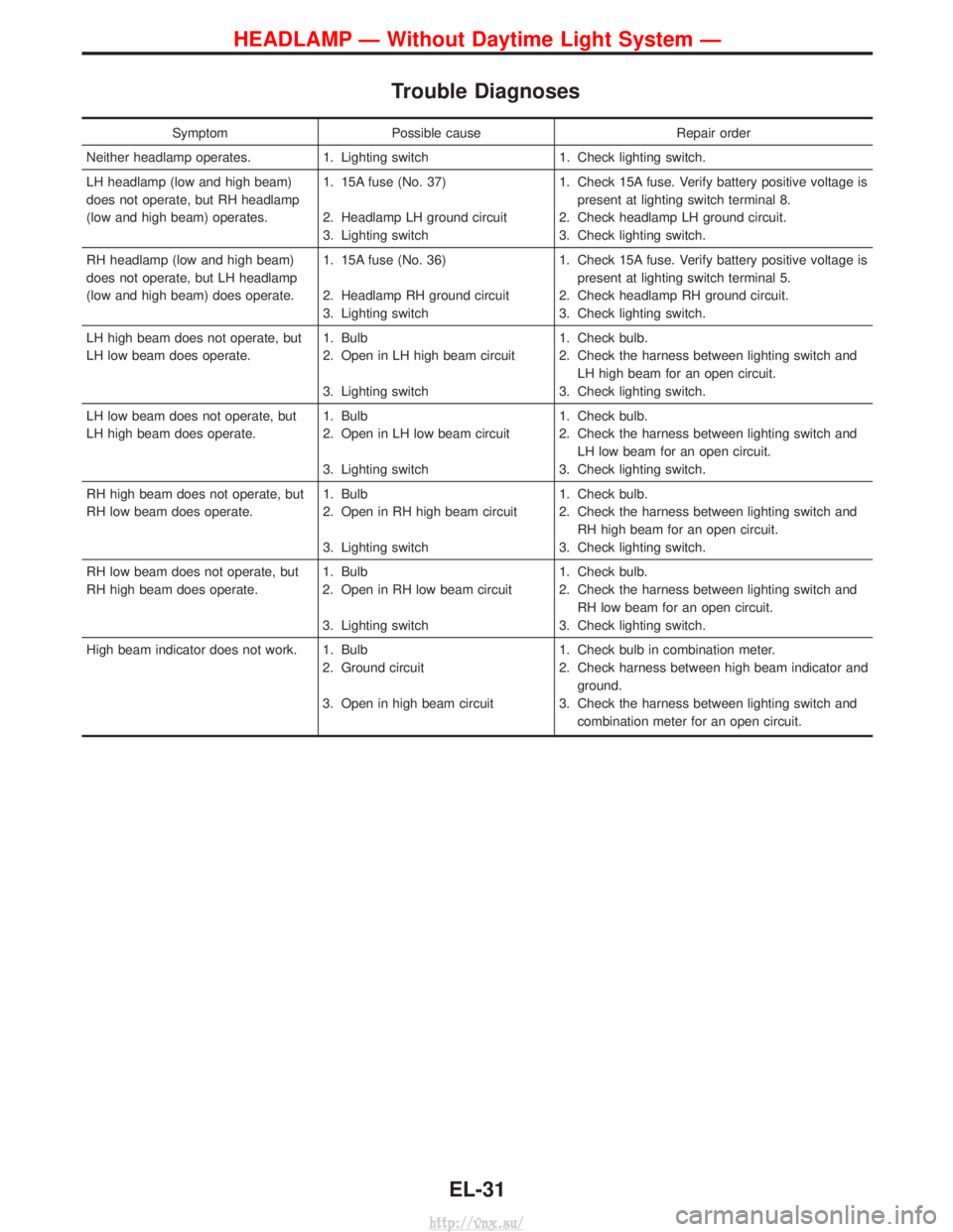
Trouble Diagnoses
SymptomPossible cause Repair order
Neither headlamp operates. 1. Lighting switch 1. Check lighting switch.
LH headlamp (low and high beam)
does not operate, but RH headlamp
(low and high beam) operates. 1. 15A fuse (No. 37)
2. Headlamp LH ground circuit
3. Lighting switch1. Check 15A fuse. Verify battery positive voltage is
present at lighting switch terminal 8.
2. Check headlamp LH ground circuit.
3. Check lighting switch.
RH headlamp (low and high beam)
does not operate, but LH headlamp
(low and high beam) does operate. 1. 15A fuse (No. 36)
2. Headlamp RH ground circuit
3. Lighting switch1. Check 15A fuse. Verify battery positive voltage is
present at lighting switch terminal 5.
2. Check headlamp RH ground circuit.
3. Check lighting switch.
LH high beam does not operate, but
LH low beam does operate. 1. Bulb
2. Open in LH high beam circuit
3. Lighting switch1. Check bulb.
2. Check the harness between lighting switch and
LH high beam for an open circuit.
3. Check lighting switch.
LH low beam does not operate, but
LH high beam does operate. 1. Bulb
2. Open in LH low beam circuit
3. Lighting switch1. Check bulb.
2. Check the harness between lighting switch and
LH low beam for an open circuit.
3. Check lighting switch.
RH high beam does not operate, but
RH low beam does operate. 1. Bulb
2. Open in RH high beam circuit
3. Lighting switch1. Check bulb.
2. Check the harness between lighting switch and
RH high beam for an open circuit.
3. Check lighting switch.
RH low beam does not operate, but
RH high beam does operate. 1. Bulb
2. Open in RH low beam circuit
3. Lighting switch1. Check bulb.
2. Check the harness between lighting switch and
RH low beam for an open circuit.
3. Check lighting switch.
High beam indicator does not work. 1. Bulb 2. Ground circuit
3. Open in high beam circuit1. Check bulb in combination meter.
2. Check harness between high beam indicator and
ground.
3. Check the harness between lighting switch and combination meter for an open circuit.
HEADLAMP Ð Without Daytime Light System Ð
EL-31
http://vnx.su/
Page 1525 of 1833
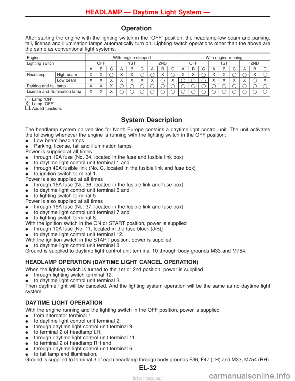
Operation
After starting the engine with the lighting switch in the ªOFFº position, the headlamp low beam and parking,
tail, license and illumination lamps automatically turn on. Lighting switch operations other than the above are
the same as conventional light systems.
EngineWith engine stopped With engine running
Lighting switch OFF 1ST 2ND OFF 1ST 2ND ABCABCABCABCABCABC
Headlamp High beam X X qXX qq Xq XX qXX qq Xq
Low beam XXXXXXX qXqqq XXXX qX
Parking and tail lamp X X Xqqqqqqqqqqqqqqq
License and illumination lamp X X X qqqqqqqqqqqqqqq
q: Lamp ªONº
X: Lamp ªOFFº
: Added functions
System Description
The headlamp system on vehicles for North Europe contains a daytime light control unit. The unit activates
the following whenever the engine is running with the lighting switch in the OFF position:
I Low beam headlamps
I Parking, license, tail and illumination lamps
Power is supplied at all times
I through 10A fuse (No. 34, located in the fuse and fusible link box)
I to daytime light control unit terminal 1 and
I through 40A fusible link (No. C, located in the fusible link and fuse box)
I to ignition switch terminal 1.
Power is also supplied at all times
I through 15A fuse (No. 36, located in the fusible link and fuse box)
I to daytime light control unit terminal 5 and
I to lighting switch terminal 5.
Power is also supplied at all times
I through 15A fuse (No. 37, located in the fusible link and fuse box)
I to daytime light control unit terminal 7 and
I to lighting switch terminal 8.
With the ignition switch in the ON or START position, power is supplied
I through 10A fuse [No. 11, located in the fuse block (J/B)]
I to daytime light control unit terminal 12.
With the ignition switch in the START position, power is supplied
I to daytime light control unit terminal 8.
Ground is supplied to daytime light control unit terminal 10 through body grounds M33 and M754.
HEADLAMP OPERATION (DAYTIME LIGHT CANCEL OPERATION)
When the lighting switch is turned to the 1st or 2nd position, power is supplied
I through lighting switch terminal 12,
I to daytime light control unit terminal 3.
Then daytime light will be canceled. And the lighting system operation will be the same as no daytime light
system.
DAYTIME LIGHT OPERATION
With the engine running and the lighting switch in the OFF position, power is supplied
I from alternator terminal 1
I to daytime light control unit terminal 2,
I through daytime light control unit terminal 9
I to terminal 2 of headlamp LH,
I through daytime light control unit terminal 11
I to terminal 2 of headlamp RH and
I through daytime light control unit terminal 6
I to tail lamp and illumination.
Ground is supplied to terminal 3 of each headlamp through body grounds F36, F47 (LH) and M33, M754 (RH).
HEADLAMP Ð Daytime Light System Ð
EL-32
http://vnx.su/
Page 1539 of 1833
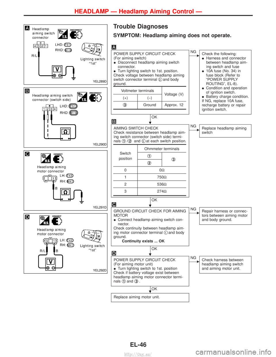
Trouble Diagnoses
SYMPTOM: Headlamp aiming does not operate.
POWER SUPPLY CIRCUIT CHECK
(For aiming switch)
IDisconnect headlamp aiming switch
connector.
I Turn lighting switch to 1st. position.
Check voltage between headlamp aiming
switch connector terminal q
3and body
ground.
OK
ENG Check the following:
IHarness and connector
between headlamp aim-
ing switch and fuse
I 10A fuse (No. 34) in
fuse block (Refer to
ªPOWER SUPPLY
ROUTINGº, EL-8).
I Condition and operation
of ignition switch.
I Battery charge condition.
If NG, replace 10A fuse,
recharge battery or repair
ignition switch.
AIMING SWITCH CHECK
Check resistance between headlamp aim-
ing switch connector (switch side) termi-
nals q
1/q2and q3at each switch position.
OK
ENG
Replace headlamp aiming
switch
GROUND CIRCUIT CHECK FOR AIMING
MOTOR
IConnect headlamp aiming switch con-
nector.
Check continuity between headlamp aim-
ing motor connector terminal q
1and body
ground. Continuity exists ... OK
OK
ENG Repair harness or connec-
tors between aiming motor
and body ground.
POWER SUPPLY CIRCUIT CHECK
(For aiming motor unit)
ITurn lighting switch to 1st. position
Check if battery voltage exist between
headlamp aiming motor connector termi-
nals q
1andq3.
OK
ENG
Check harness between
headlamp aiming switch
and aiming motor unit.
Replace aiming motor unit.
Voltmeter terminals
Voltage (V)
(+) (þ)
q
3Ground Approx. 12
Switch
position Ohmmeter terminals
q1q3q2
00 W
1 750W
2 536W
3 274W
YEL289D
YEL290D
YEL291D
YEL292D
H
H
H
H
HEADLAMP Ð Headlamp Aiming Control Ð
EL-46
http://vnx.su/
Page 1552 of 1833
![NISSAN TERRANO 2004 Service Repair Manual System Description
TURN SIGNAL OPERATION
Power is supplied at all times
Ithrough 10A fuse [No. 5, located in fuse block (J/B)]
I to time control unit terminal U09, and
With the ignition switch in the NISSAN TERRANO 2004 Service Repair Manual System Description
TURN SIGNAL OPERATION
Power is supplied at all times
Ithrough 10A fuse [No. 5, located in fuse block (J/B)]
I to time control unit terminal U09, and
With the ignition switch in the](/manual-img/5/57394/w960_57394-1551.png)
System Description
TURN SIGNAL OPERATION
Power is supplied at all times
Ithrough 10A fuse [No. 5, located in fuse block (J/B)]
I to time control unit terminal U09, and
With the ignition switch in the ON or START position, power is supplied
I through 10A fuse [No. 26, located in fuse block (J/B)]
I to time control unit terminal U01
Ground is supplied to time control unit terminal U16
I through fuse block (J/B) terminal MM2
I through body grounds F36 and F47 (LHD models) or
I through body grounds M33 and M754 (RHD models).
LH Turn
When the turn signal switch is turned to the L position, ground is supplied from body grounds M33 and M754
Ito time control unit terminal U02
I through fuse block (J/B) terminal E03
I through turn signal switch terminals 3 and 1
With ground is supplied, time control unit controls the flashing of the LH turn signal lamps.
Power is supplied from time control unit terminal U15
I to front turn signal lamp LH terminal 2,
I to side turn signal lamp LH terminal 2 and
I to rear combination lamp LH terminal 1
Ground is supplied to the front turn signal lamp LH terminal 1 through body grounds F36 and F47.
Ground is supplied to the side turn signal lamp LH terminal 1 through body grounds F36 and F47.
Ground is supplied to the rear combination lamp LH terminal 4 through body grounds B10 and B18.
RH Turn
When the turn signal switch is turned to the R position, ground is supplied from body grounds M33 and M754
I to time control unit terminal U04
I through fuse block (J/B) terminal E18
I through turn signal switch terminals 2 and 1
With ground is supplied, time control unit controls the flashing of the RH turn signal lamps.
Power is supplied from time control unit terminal U11
I to front turn signal lamp RH terminal 2,
I to side turn signal lamp RH terminal 2 and
I to rear combination lamp RH terminal 1
Ground is supplied to the front turn signal lamp RH terminal 1 through body grounds M33 and M754.
Ground is supplied to the side turn signal lamp RH terminal 1 through body grounds M33 and M754.
Ground is supplied to the rear combination lamp RH terminal 4 through body grounds B10 and B18.
HAZARD LAMP OPERATION
With the hazard switch in the ON position, ground is supplied from body grounds F36, F47 (LHD models) or
M33, M754 (RHD models)
I to time control unit terminal U05
I through fuse block (J/B) terminal M46
I through hazard switch terminals 17 and 19
With ground is supplied, time control unit controls the flashing of the hazard warning lamps.
Power is supplied from time control unit terminal U15
I to front turn signal lamp LH terminal 2,
I to side turn signal lamp LH terminal 2 and
I to rear combination lamp LH terminal 1
Power is supplied from time control unit terminal U11
I to front turn signal lamp RH terminal 2,
I to side turn signal lamp RH terminal 2 and
I to rear combination lamp RH terminal 1
Ground is supplied to terminal 1 of each front turn signal lamp through body grounds F36, F47 (LHD models)
or M33, M754 (RHD models).
Ground is supplied to terminal 1 of each side turn signal lamp through body grounds F36, F47 (LHD models)
EXTERIOR LAMP
EL-59
http://vnx.su/
Page 1559 of 1833
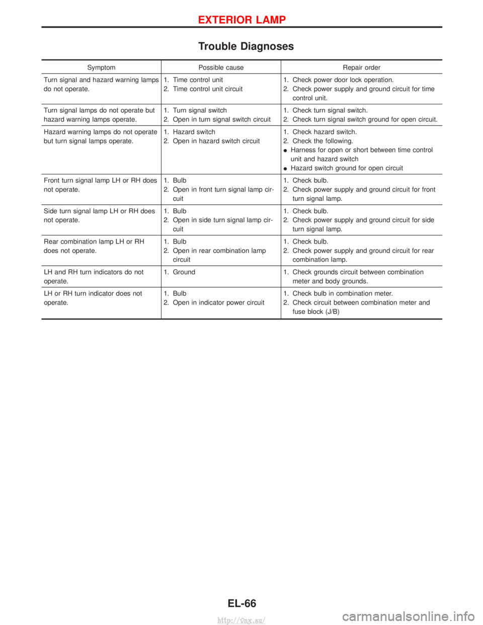
Trouble Diagnoses
SymptomPossible cause Repair order
Turn signal and hazard warning lamps
do not operate. 1. Time control unit
2. Time control unit circuit1. Check power door lock operation.
2. Check power supply and ground circuit for time
control unit.
Turn signal lamps do not operate but
hazard warning lamps operate. 1. Turn signal switch
2. Open in turn signal switch circuit1. Check turn signal switch.
2. Check turn signal switch ground for open circuit.
Hazard warning lamps do not operate
but turn signal lamps operate. 1. Hazard switch
2. Open in hazard switch circuit1. Check hazard switch.
2. Check the following.
I
Harness for open or short between time control
unit and hazard switch
I Hazard switch ground for open circuit
Front turn signal lamp LH or RH does
not operate. 1. Bulb
2. Open in front turn signal lamp cir-
cuit 1. Check bulb.
2. Check power supply and ground circuit for front
turn signal lamp.
Side turn signal lamp LH or RH does
not operate. 1. Bulb
2. Open in side turn signal lamp cir-
cuit 1. Check bulb.
2. Check power supply and ground circuit for side
turn signal lamp.
Rear combination lamp LH or RH
does not operate. 1. Bulb
2. Open in rear combination lamp
circuit 1. Check bulb.
2. Check power supply and ground circuit for rear
combination lamp.
LH and RH turn indicators do not
operate. 1. Ground
1. Check grounds circuit between combination
meter and body grounds.
LH or RH turn indicator does not
operate. 1. Bulb
2. Open in indicator power circuit1. Check bulb in combination meter.
2. Check circuit between combination meter and
fuse block (J/B)
EXTERIOR LAMP
EL-66
http://vnx.su/
Page 1565 of 1833
![NISSAN TERRANO 2004 Service Repair Manual System Description
POWER SUPPLY AND GROUND
Power is supplied at all times:
Ithrough 15A fuse [No. 5, located in the fuse block (J/B)]
I to time control unit terminal U09,
I through 10A fuse [No. 16, l NISSAN TERRANO 2004 Service Repair Manual System Description
POWER SUPPLY AND GROUND
Power is supplied at all times:
Ithrough 15A fuse [No. 5, located in the fuse block (J/B)]
I to time control unit terminal U09,
I through 10A fuse [No. 16, l](/manual-img/5/57394/w960_57394-1564.png)
System Description
POWER SUPPLY AND GROUND
Power is supplied at all times:
Ithrough 15A fuse [No. 5, located in the fuse block (J/B)]
I to time control unit terminal U09,
I through 10A fuse [No. 16, located in the fuse block (J/B)]
I to front interior lamp terminal 1,
I to rear interior lamp terminal 1 (Wagon models)
I to rear room lamp terminal 2 (Hardtop models)
I to sunroof switch and map lamps terminal 3 (with sunroof),
I to map lamp terminal 2 (without sunroof).
Ground is supplied:
I through body grounds terminals F36, F47 (LHD models) or M33, M754 (RHD models).
I through fuse block terminal MM2
I to time control unit terminal U16
When the driver side door is opened, ground is supplied:
I through driver side door switch case ground and terminal 1, and
I through fuse block terminal B07
I to time control unit terminal U06
When any door is opened, ground is supplied:
I through case ground and terminal 1 of each door switch,
I through fuse block terminal B01
I to time control unit terminal U07.
When the driver side door is unlocked by the door lock/unlock switch, the time control unit receives a ground
signal:
I through body grounds B10 and B18
I to power window main switch terminal 3
I from power window main switch terminal 7
I to time control unit terminal U37.
When a signal, or combination of signals is received by the time control unit, ground is supplied:
I through time control unit terminal U12 and fuse block terminal R01
I to front interior room lamp terminal 2.
I to rear interior lamp terminal 2 (Wagon models).
I to rear interior room lamp terminal 1 (Hardtop models).
With power and ground supplied, the interior room lamps illuminate when the lamp switch is in ªDOORº posi-
tion.
SWITCH OPERATION
When interior room lamp switch is in ªONº position, ground is supplied:
I through front interior lamp case ground.
I through rear interior lamp case ground (Wagon models).
When sunroof switch and map lamps (with sunroof) is ON, ground is supplied:
I through body grounds F36, F47 (LHD models) or M33, M754 (RHD models)
I through fuse block terminal MM2 and R03
I to sunroof switch map lamps terminal 2.
When map lamp (without sunroof) is ON, ground is supplied:
I through body grounds F36, F47 (LHD models) or M33, M754 (RHD models)
I through fuse block terminal MM2 and R03
I to map lamp terminal 1.
With power and ground supplied, the interior room lamps, map lamps illuminate.
INTERIOR ROOM LAMP TIMER OPERATION
When interior room lamp switch is in the ªDOORº position, the time control unit keeps the interior room lamp
illuminated for about 30 seconds when:
I unlock signal is supplied from door lock/unlock switch while all doors are closed
I unlock signal is supplied from remote controller or door key cylinder while all doors are closed
I driver's door is opened and then closed
The timer is canceled when:
I driver's door is locked,
INTERIOR LAMP
EL-72
http://vnx.su/
Page 1571 of 1833
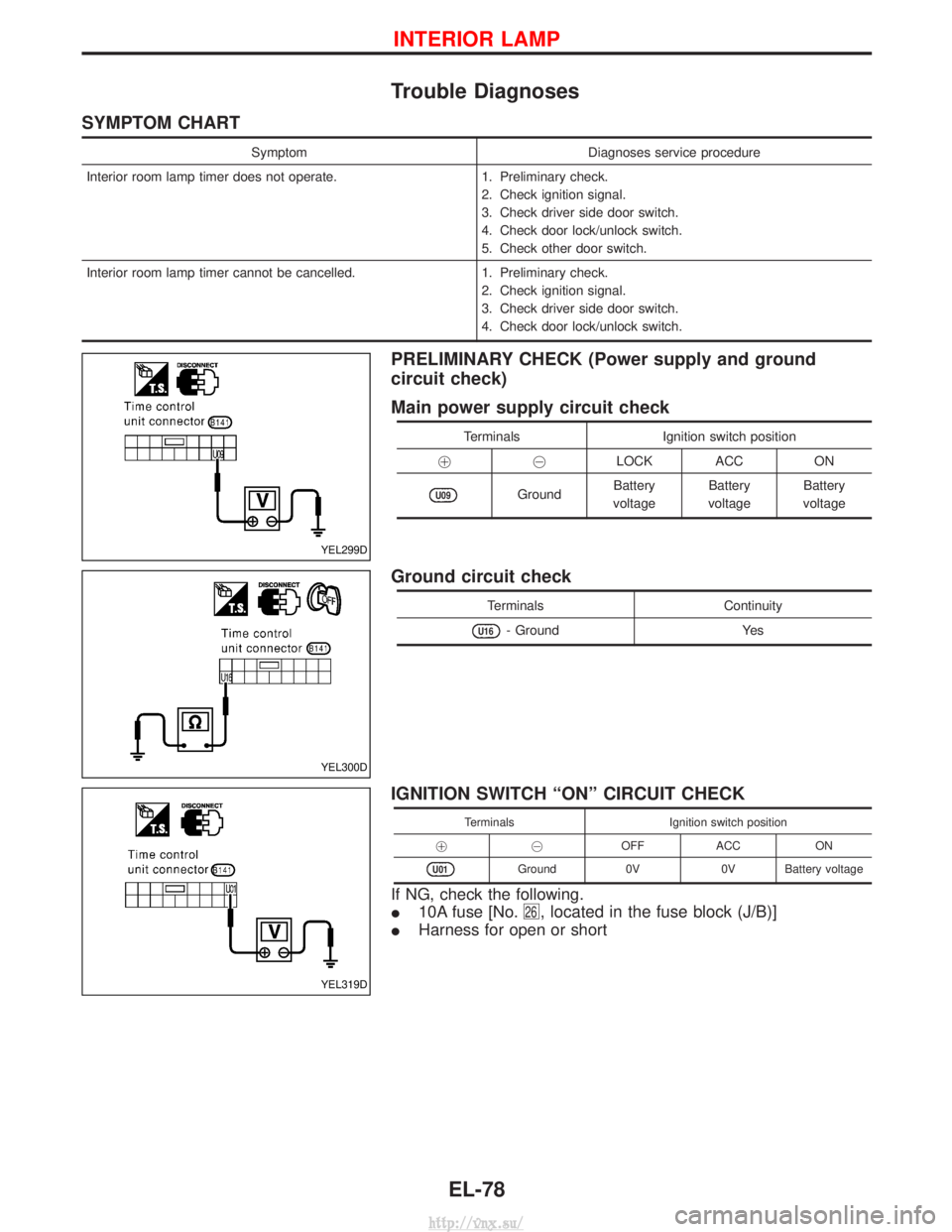
Trouble Diagnoses
SYMPTOM CHART
SymptomDiagnoses service procedure
Interior room lamp timer does not operate. 1. Preliminary check.
2. Check ignition signal.
3. Check driver side door switch.
4. Check door lock/unlock switch.
5. Check other door switch.
Interior room lamp timer cannot be cancelled. 1. Preliminary check.
2. Check ignition signal.
3. Check driver side door switch.
4. Check door lock/unlock switch.
PRELIMINARY CHECK (Power supply and ground
circuit check)
Main power supply circuit check
Terminals Ignition switch position
!@ LOCK ACC ON
U09GroundBattery
voltage Battery
voltage Battery
voltage
Ground circuit check
Terminals Continuity
U16- GroundYes
IGNITION SWITCH ªONº CIRCUIT CHECK
TerminalsIgnition switch position
!@ OFFACC ON
U01Ground 0V0V Battery voltage
If NG, check the following.
I10A fuse [No.
26, located in the fuse block (J/B)]
IHarness for open or short
YEL299D
YEL300D
YEL319D
INTERIOR LAMP
EL-78
http://vnx.su/