2004 NISSAN TERRANO oil level
[x] Cancel search: oil levelPage 576 of 1833
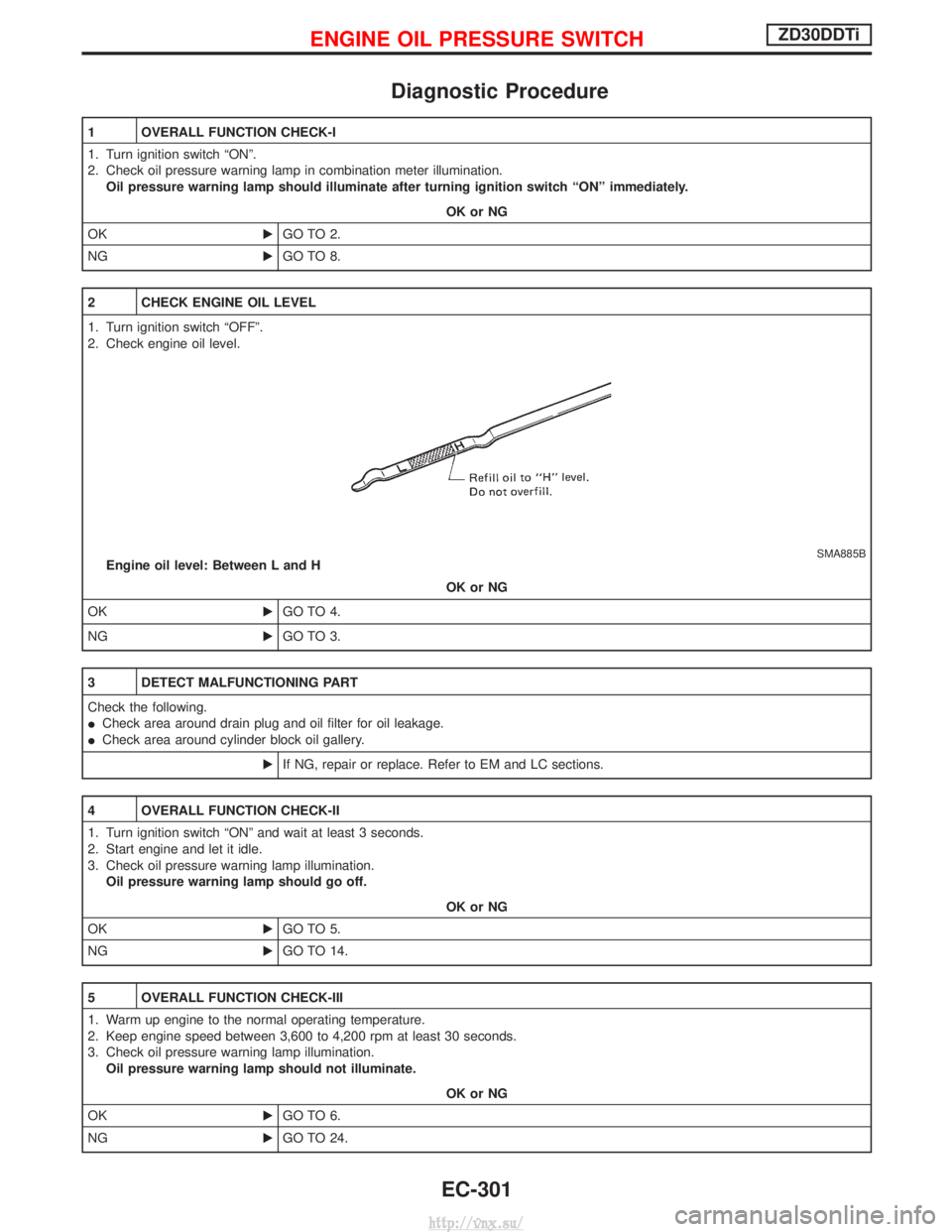
Diagnostic Procedure
1 OVERALL FUNCTION CHECK-I
1. Turn ignition switch ªONº.
2. Check oil pressure warning lamp in combination meter illumination.Oil pressure warning lamp should illuminate after turning ignition switch ªONº immediately.
OK or NG
OK EGO TO 2.
NG EGO TO 8.
2 CHECK ENGINE OIL LEVEL
1. Turn ignition switch ªOFFº.
2. Check engine oil level.
SMA885BEngine oil level: Between L and H
OK or NG
OK EGO TO 4.
NG EGO TO 3.
3 DETECT MALFUNCTIONING PART
Check the following.
ICheck area around drain plug and oil filter for oil leakage.
I Check area around cylinder block oil gallery.
EIf NG, repair or replace. Refer to EM and LC sections.
4 OVERALL FUNCTION CHECK-II
1. Turn ignition switch ªONº and wait at least 3 seconds.
2. Start engine and let it idle.
3. Check oil pressure warning lamp illumination.
Oil pressure warning lamp should go off.
OK or NG
OK EGO TO 5.
NG EGO TO 14.
5 OVERALL FUNCTION CHECK-III
1. Warm up engine to the normal operating temperature.
2. Keep engine speed between 3,600 to 4,200 rpm at least 30 seconds.
3. Check oil pressure warning lamp illumination.
Oil pressure warning lamp should not illuminate.
OK or NG
OK EGO TO 6.
NG EGO TO 24.
ENGINE OIL PRESSURE SWITCHZD30DDTi
EC-301
http://vnx.su/
Page 716 of 1833
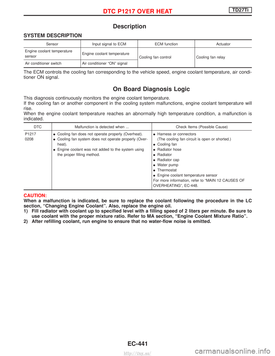
Description
SYSTEM DESCRIPTION
SensorInput signal to ECM ECM functionActuator
Engine coolant temperature
sensor Engine coolant temperature
Cooling fan control Cooling fan relay
Air conditioner switch Air conditioner ªONº signal
The ECM controls the cooling fan corresponding to the vehicle speed, engine coolant temperature, air condi-
tioner ON signal.
On Board Diagnosis Logic
This diagnosis continuously monitors the engine coolant temperature.
If the cooling fan or another component in the cooling system malfunctions, engine coolant temperature will
rise.
When the engine coolant temperature reaches an abnormally high temperature condition, a malfunction is
indicated.
DTC Malfunction is detected when ... Check Items (Possible Cause)
P1217
0208 I
Cooling fan does not operate properly (Overheat).
I Cooling fan system does not operate properly (Over-
heat).
I Engine coolant was not added to the system using
the proper filling method. I
Harness or connectors
(The cooling fan circuit is open or shorted.)
I Cooling fan
I Radiator hose
I Radiator
I Radiator cap
I Water pump
I Thermostat
I Engine coolant temperature sensor
For more information, refer to ªMAIN 12 CAUSES OF
OVERHEATINGº, EC-448.
CAUTION:
When a malfunction is indicated, be sure to replace the coolant following the procedure in the LC
section, ªChanging Engine Coolantº. Also, replace the engine oil.
1) Fill radiator with coolant up to specified level with a filling speed of 2 liters per minute. Be sure to use coolant with the proper mixture ratio. Refer to MA section, ªEngine Coolant Mixture Ratioº.
2) After refilling coolant, run engine to ensure that no water-flow noise is emitted.
DTC P1217 OVER HEATTD27Ti
EC-441
http://vnx.su/
Page 840 of 1833

A/T Fluid Check
FLUID LEAKAGE CHECK
1. Clean area suspected of leaking. Ð for example, mating sur-face of converter housing and transmission case.
2. Start engine, apply foot brake, place selector lever in ªDº posi- tion and wait a few minutes.
3. Stop engine.
4. Check for fresh leakage.
FLUID CONDITION CHECK
Fluid color Suspected cause
Dark or black with burned odor Wear of frictional material
Milky pink Water contamination Ð Road water enter-
ing through filler tube or breather
Varnished fluid, light to dark
brown and tacky Oxidation Ð Over or under filling, Ð Over-
heating
FLUID LEVEL CHECK
Refer to MA section (ªChecking A/T Fluidº, ªCHASSIS AND BODY
MAINTENANCEº).
Stall Test
STALL TEST PROCEDURE
1. Check A/T and engine fluid levels. If necessary, add.
2. Drive vehicle for approx. 10 minutes or until engine oil and ATF
reach operating temperature.ATF operating temperature: 50 - 80ÉC (122 - 176ÉF)
3. Set parking brake and block wheels.
4. Install a tachometer where it can be seen by driver during test.
I It is good practice to put a mark on point of specified
engine rpm on indicator.
5. Start engine, apply foot brake, and place selector lever in ªDº position.
6. Accelerate to wide open throttle gradually while applying foot brake.
7. Quickly note the engine stall revolution and immediately release throttle.
I During test, never hold throttle wide open for more than 5
seconds.
Stall revolution: 2,450 - 2,700 rpm
SAT801A
SAT638A
SAT647B
SAT513G
SAT514G
TROUBLE DIAGNOSIS Ð Basic Inspection
AT-27
http://vnx.su/
Page 843 of 1833
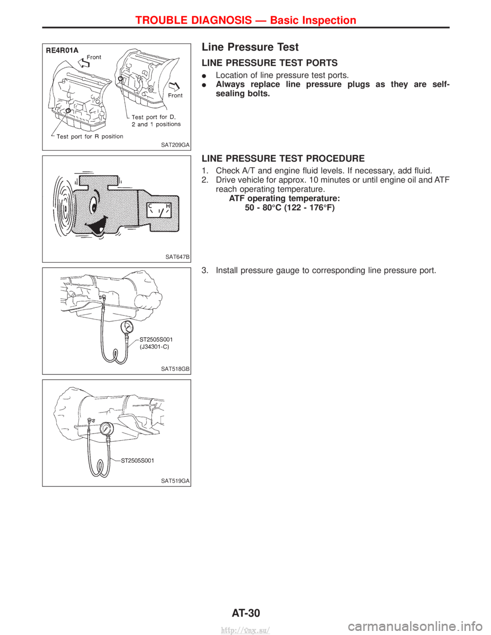
Line Pressure Test
LINE PRESSURE TEST PORTS
ILocation of line pressure test ports.
I Always replace line pressure plugs as they are self-
sealing bolts.
LINE PRESSURE TEST PROCEDURE
1. Check A/T and engine fluid levels. If necessary, add fluid.
2. Drive vehicle for approx. 10 minutes or until engine oil and ATF
reach operating temperature.ATF operating temperature: 50 - 80ÉC (122 - 176ÉF)
3. Install pressure gauge to corresponding line pressure port.
SAT209GA
SAT647B
SAT518GB
SAT519GA
TROUBLE DIAGNOSIS Ð Basic Inspection
AT-30
http://vnx.su/
Page 856 of 1833
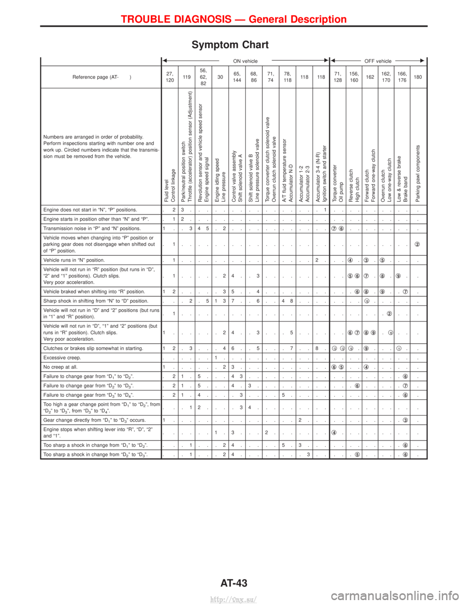
Symptom Chart
FON vehicleEFOFF vehicleE
Reference page (AT- )27,
120 11 9 56,
62,
82 30
65,
144 68,
86 71,
74 78,
11 8 11 8 11 8 71,
128 156,
160 162162,
170 166,
176 180
Numbers are arranged in order of probability.
Perform inspections starting with number one and
work up. Circled numbers indicate that the transmis-
sion must be removed from the vehicle.
Fluid level
Control linkage
Park/neutral position switch
Throttle (accelerator) position sensor (Adjustment)
Revolution sensor and vehicle speed sensor
Engine speed signal
Engine idling speed
Line pressure
Control valve assembly
Shift solenoid valve A
Shift solenoid valve B
Line pressure solenoid valve
Torque converter clutch solenoid valve
Overrun clutch solenoid valve
A/T fluid temperature sensor
Accumulator N-D
Accumulator 1-2
Accumulator 2-3
Accumulator 3-4 (N-R)
Ignition switch and starter
Torque converter
Oil pump
Reverse clutch
High clutch
Forward clutch
Forward one-way clutch
Overrun clutch
Low one-way clutch
Low & reverse brake
Brake band
Parking pawl components
Engine does not start in ªNº, ªPº positions. . 2 3................1. ......... .
Engine starts in position other than ªNº and ªPº. . 1 2 ................. . ......... .
Transmission noise in ªPº and ªNº positions. 1 . . 3 4 5 . 2 ............q
7q6........ .
Vehicle moves when changing into ªPº position or
parking gear does not disengage when shifted out
of ªPº position. . 1.................. .
.........q
2
Vehicle runs in ªNº position.
. 1................2. .. q4.q3.q5... .
Vehicle will not run in ªRº position (but runs in ªDº,
ª2º and ª1º positions). Clutch slips.
Very poor acceleration. . 1.....24..3........ ..
q
5q6q7.q8.q9..
Vehicle braked when shifting into ªRº position. 1 2 .....35..4........ ... q
6q8.q9.. q7.
Sharp shock in shifting from ªNº to ªDº position. . . . 2 . 5137 . . 6 . . 48.... ....q
10..... .
Vehicle will not run in ªDº and ª2º positions (but runs
in ª1º and ªRº position). . 1.................. .
......q
2.. .
Vehicle will not run in ªDº, ª1º and ª2º positions (but
runs in ªRº position). Clutch slips.
Very poor acceleration. 1 ......24..3...5.... ..
q
6q7q8q9.q10.. .
Clutches or brakes slip somewhat in starting. 1 2 . 3 . . . 4 6 . . 5 . . . 7 . . 8 . q
13q12q10.q9... q11..
Excessive creep. . .....1............. . ......... .
No creep at all. 1 ......23........... q
6q5..q4..... .
Failure to change gear from ªD
1ºtoªD2º. . 21.5...43.......... . ........q6.
Failure to change gear from ªD
2ºtoªD3º. . 21.5...4.3......... ... q6.....q7.
Failure to change gear from ªD
3ºtoªD4º. . 21.4....3....5..... . ........q6.
Too high a gear change point from ªD
1ºtoªD2º, from
ªD2ºtoªD3º, from ªD3ºtoªD4º. . ..12....34......... .
......... .
Gear change directly from ªD
1ºtoªD3º occurs. 1 ...............2... . ........q3.
Engine stops when shifting lever into ªRº, ªDº, ª2º
and ª1º. . .....1.3...2.......
q
4......... .
Too sharp a shock in change from ªD
1ºtoªD2º. . ..1...24.....5.3... . ........q6.
Too sharp a shock in change from ªD
2ºtoªD3º. . ..1...24........3.. ... q5.....q6.
TROUBLE DIAGNOSIS Ð General Description
AT-43
http://vnx.su/
Page 857 of 1833
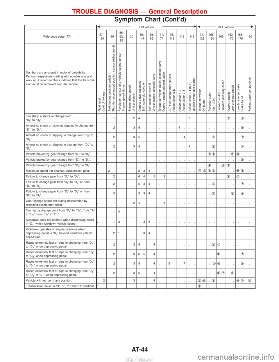
FON vehicleEFOFF vehicleE
Reference page (AT- )27,
120 11 9 56,
62,
82 30
65,
144 68,
86 71,
74 78,
11 8 11 8 11 8 71,
128 156,
160 162162,
170 166,
176 180
Numbers are arranged in order of probability.
Perform inspections starting with number one and
work up. Circled numbers indicate that the transmis-
sion must be removed from the vehicle.
Fluid level
Control linkage
Park/neutral position switch
Throttle (accelerator) position sensor (Adjustment)
Revolution sensor and vehicle speed sensor
Engine speed signal
Engine idling speed
Line pressure
Control valve assembly
Shift solenoid valve A
Shift solenoid valve B
Line pressure solenoid valve
Torque converter clutch solenoid valve
Overrun clutch solenoid valve
A/T fluid temperature sensor
Accumulator N-D
Accumulator 1-2
Accumulator 2-3
Accumulator 3-4 (N-R)
Ignition switch and starter
Torque converter
Oil pump
Reverse clutch
High clutch
Forward clutch
Forward one-way clutch
Overrun clutch
Low one-way clutch
Low & reverse brake
Brake band
Parking pawl components
Too sharp a shock in change from
ªD3ºtoªD4º. . ..1...24.........3. .
.....q6..q5.
Almost no shock or clutches slipping in change from
ªD
1ºtoªD2º. 1 ..2...35.......4... .
........q6.
Almost no shock or slipping in change from ªD
2ºto
ªD3º. 1 ..2...35........4.. ...
q6.....q7.
Almost no shock or slipping in change from ªD
3ºto
ªD4º. 1 ..2...35.........4. ...
q6.....q7.
Vehicle braked by gear change from ªD
1ºtoªD2º. 1 ................... .. q2q4...q5q3..
Vehicle braked by gear change from ªD
2ºtoªD3º. 1 ................... . ........q2.
Vehicle braked by gear change from ªD
3ºtoªD4º. 1 ................... .. q4..q3q2... .
Maximum speed not attained. Acceleration poor. 1 . 2 .....534.........q
11q10q6q7....q9q8.
Failure to change gear from ªD
4ºtoªD3º. 1 ..2....64.5.3...... . .....q8.q7..
Failure to change gear from ªD
3ºtoªD2º or from
ªD4ºtoªD2º. 1 ..2....534......... ...
q6.....q7.
Failure to change gear from ªD
2ºtoªD1º or from
ªD3ºtoªD1º. 1 ..2....534......... ...
q7...q6.q8.
Gear change shock felt during deceleration by
releasing accelerator pedal. . ..1...24....3...... .
......... .
Too high a change point from ªD
4ºtoªD3º, from ªD3º
to ªD2º, from ªD2ºtoªD1º. . ..12............... .
......... .
Kickdown does not operate when depressing pedal
in ªD
4º within kickdown vehicle speed. . ..12....34......... .
......... .
Kickdown operates or engine overruns when
depressing pedal in ªD
4º beyond kickdown vehicle
speed limit. . ..21....34......... .
......... .
Races extremely fast or slips in changing from ªD
4º
to ªD3º when depressing pedal. 1 ..2...35..4........ ...
q6q7..... .
Races extremely fast or slips in changing from ªD
4º
to ªD2º when depressing pedal. 1 ..2...365.4........ ....
q8....q7.
Races extremely fast or slips in changing from ªD
3º
to ªD2º when depressing pedal. 1 ..2...35..4..6..7.. ...
q10q9....q8.
Races extremely fast or slips in changing from ªD
4º
or ªD3ºtoªD1º when depressing pedal. 1 ..2...35..4........ ....
q6q7.q8.. .
Vehicle will not run in any position. 1 2 .....3...4........ q
9q5.q6.... q8q7q10
Transmission noise in ªDº, ª2º, ª1º and ªRº positions. 1
................... q2......... .
TROUBLE DIAGNOSIS Ð General Description
Symptom Chart (Cont'd)
AT-44
http://vnx.su/
Page 858 of 1833
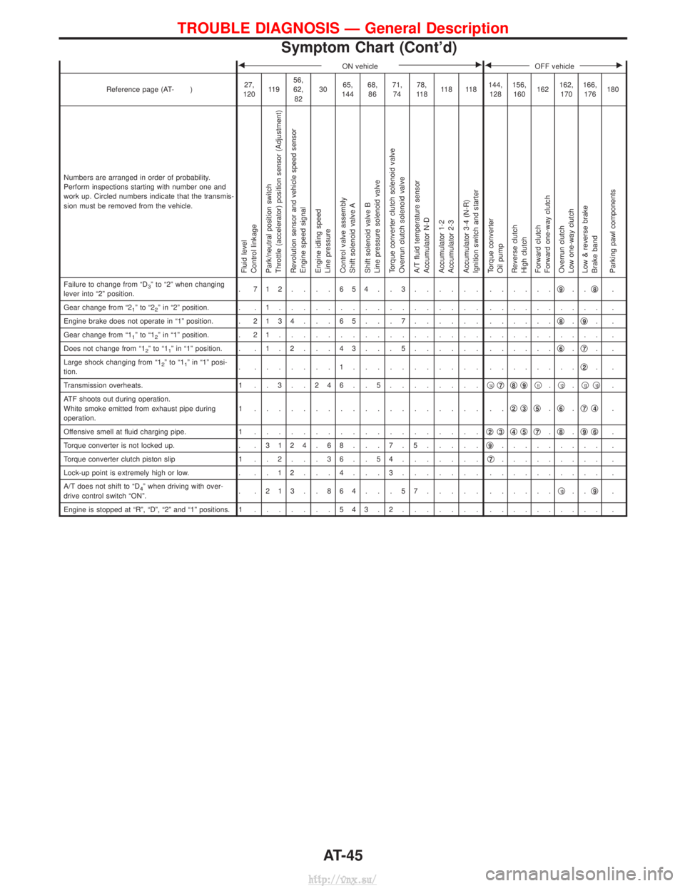
FON vehicleEFOFF vehicleE
Reference page (AT- )27,
120 11 9 56,
62,
82 30
65,
144 68,
86 71,
74 78,
11 8 11 8 11 8 144,
128 156,
160 162162,
170 166,
176 180
Numbers are arranged in order of probability.
Perform inspections starting with number one and
work up. Circled numbers indicate that the transmis-
sion must be removed from the vehicle.
Fluid level
Control linkage
Park/neutral position switch
Throttle (accelerator) position sensor (Adjustment)
Revolution sensor and vehicle speed sensor
Engine speed signal
Engine idling speed
Line pressure
Control valve assembly
Shift solenoid valve A
Shift solenoid valve B
Line pressure solenoid valve
Torque converter clutch solenoid valve
Overrun clutch solenoid valve
A/T fluid temperature sensor
Accumulator N-D
Accumulator 1-2
Accumulator 2-3
Accumulator 3-4 (N-R)
Ignition switch and starter
Torque converter
Oil pump
Reverse clutch
High clutch
Forward clutch
Forward one-way clutch
Overrun clutch
Low one-way clutch
Low & reverse brake
Brake band
Parking pawl components
Failure to change from ªD3º to ª2º when changing
lever into ª2º position. . 712....654..3...... .
.....q9..q8.
Gear change from ª2
1ºtoª22º in ª2º position. . . 1 ................. . ......... .
Engine brake does not operate in ª1º position. . 2134 . . . 65 . . . 7...... ......q
8.q9..
Gear change from ª1
1ºtoª12º in ª1º position. . 2 1 ................. . ......... .
Does not change from ª1
2ºtoª11º in ª1º position. . . 1 . 2 . . . 4 3 . . . 5 ...... ......q6.q7..
Large shock changing from ª1
2ºtoª11º in ª1º posi-
tion. . .......1........... .
.......q2..
Transmission overheats. 1 . . 3 . . 2 4 6 . . 5 ........q
14q7q8q9q11.q12.q13q10.
ATF shoots out during operation.
White smoke emitted from exhaust pipe during
operation. 1 ................... ..
q
2q3q5.q6.q7q4.
Offensive smell at fluid charging pipe. 1 ................... q
2q3q4q5q7.q8.q9q6.
Torque converter is not locked up. . . 3124 . 68 . . . 7 . 5.....q
9......... .
Torque converter clutch piston slip 1 . . 2 . . . 3 6 . . 5 4 .......q
7......... .
Lock-up point is extremely high or low. . . . 1 2 . . . 4 . . . 3 ....... .......... .
A/T does not shift to ªD
4º when driving with over-
drive control switch ªONº. . .213..864...57..... .
.....q10..q9.
Engine is stopped at ªRº, ªDº, ª2º and ª1º positions. 1 .......543.2....... . ......... .
TROUBLE DIAGNOSIS Ð General Description
Symptom Chart (Cont'd)
AT-45
http://vnx.su/
Page 916 of 1833
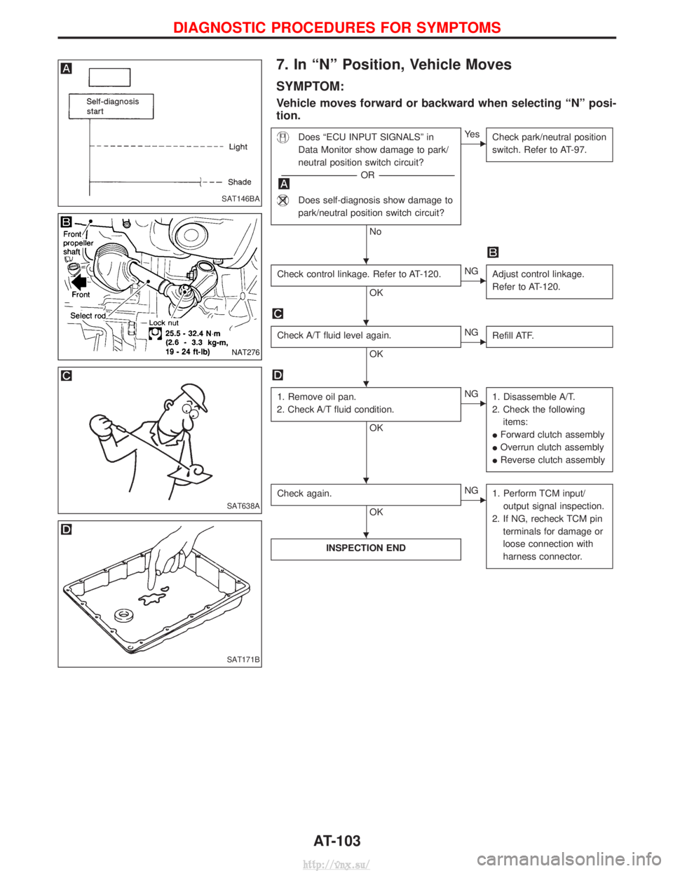
7. In ªNº Position, Vehicle Moves
SYMPTOM:
Vehicle moves forward or backward when selecting ªNº posi-
tion.
Does ªECU INPUT SIGNALSº in
Data Monitor show damage to park/
neutral position switch circuit?
---------------------------------------------------------------------------------------------------------------------- -OR -----------------------------------------------------------------------------------------------------------------------
Does self-diagnosis show damage to
park/neutral position switch circuit?
No
EYe s
Check park/neutral position
switch. Refer to AT-97.
Check control linkage. Refer to AT-120.
OK
ENGAdjust control linkage.
Refer to AT-120.
Check A/T fluid level again.
OK
ENGRefill ATF.
1. Remove oil pan.
2. Check A/T fluid condition.
OK
ENG 1. Disassemble A/T.
2. Check the following items:
I Forward clutch assembly
I Overrun clutch assembly
I Reverse clutch assembly
Check again.
OK
ENG
1. Perform TCM input/
output signal inspection.
2. If NG, recheck TCM pin terminals for damage or
loose connection with
harness connector.
INSPECTION END
SAT146BA
NAT276
SAT638A
SAT171B
H
H
H
HH
H
DIAGNOSTIC PROCEDURES FOR SYMPTOMS
AT-103
http://vnx.su/