2004 NISSAN TERRANO oil level
[x] Cancel search: oil levelPage 1407 of 1833
Refrigeration Cycle
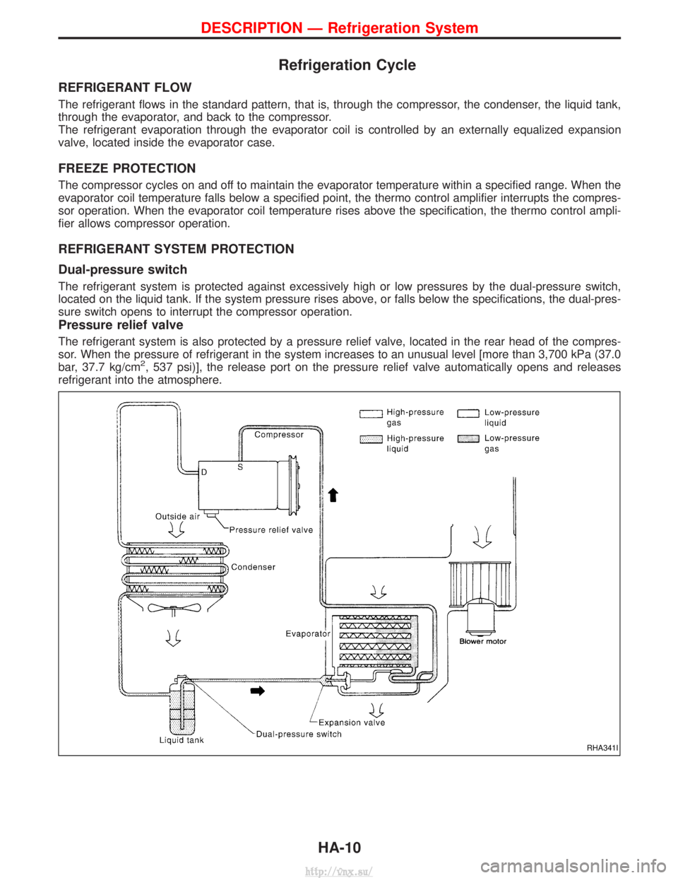
REFRIGERANT FLOW
The refrigerant flows in the standard pattern, that is, through the compressor, the condenser, the liquid tank,
through the evaporator, and back to the compressor.
The refrigerant evaporation through the evaporator coil is controlled by an externally equalized expansion
valve, located inside the evaporator case.
FREEZE PROTECTION
The compressor cycles on and off to maintain the evaporator temperature within a specified range. When the
evaporator coil temperature falls below a specified point, the thermo control amplifier interrupts the compres-
sor operation. When the evaporator coil temperature rises above the specification, the thermo control ampli-
fier allows compressor operation.
REFRIGERANT SYSTEM PROTECTION
Dual-pressure switch
The refrigerant system is protected against excessively high or low pressures by the dual-pressure switch,
located on the liquid tank. If the system pressure rises above, or falls below the specifications, the dual-pres-
sure switch opens to interrupt the compressor operation.
Pressure relief valve
The refrigerant system is also protected by a pressure relief valve, located in the rear head of the compres-
sor. When the pressure of refrigerant in the system increases to an unusual level [more than 3,700 kPa (37.0
bar, 37.7 kg/cm
2, 537 psi)], the release port on the pressure relief valve automatically opens and releases
refrigerant into the atmosphere.
RHA341I
DESCRIPTION Ð Refrigeration System
HA-10
http://vnx.su/
Page 1540 of 1833
Bulb Replacement
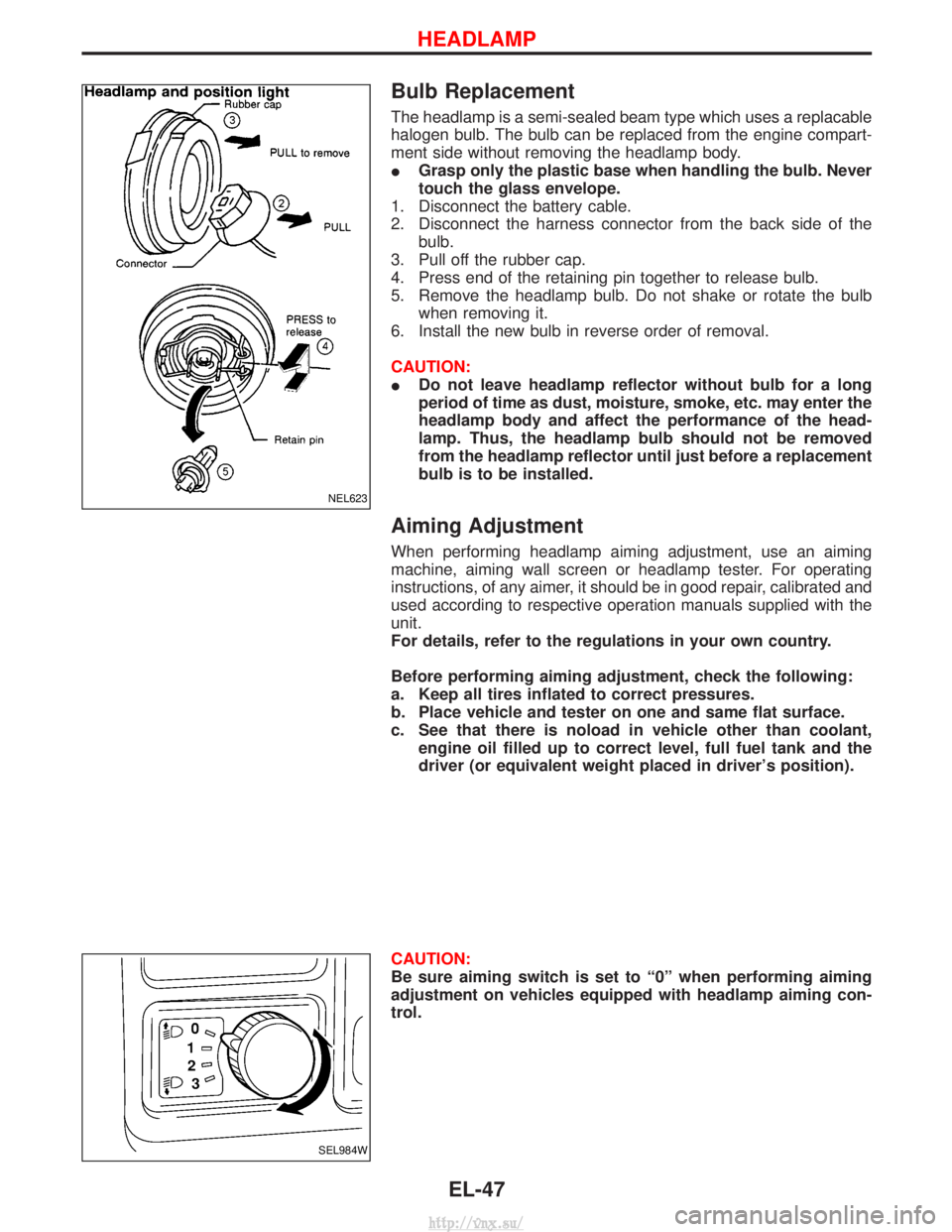
The headlamp is a semi-sealed beam type which uses a replacable
halogen bulb. The bulb can be replaced from the engine compart-
ment side without removing the headlamp body.
IGrasp only the plastic base when handling the bulb. Never
touch the glass envelope.
1. Disconnect the battery cable.
2. Disconnect the harness connector from the back side of the bulb.
3. Pull off the rubber cap.
4. Press end of the retaining pin together to release bulb.
5. Remove the headlamp bulb. Do not shake or rotate the bulb when removing it.
6. Install the new bulb in reverse order of removal.
CAUTION:
I Do not leave headlamp reflector without bulb for a long
period of time as dust, moisture, smoke, etc. may enter the
headlamp body and affect the performance of the head-
lamp. Thus, the headlamp bulb should not be removed
from the headlamp reflector until just before a replacement
bulb is to be installed.
Aiming Adjustment
When performing headlamp aiming adjustment, use an aiming
machine, aiming wall screen or headlamp tester. For operating
instructions, of any aimer, it should be in good repair, calibrated and
used according to respective operation manuals supplied with the
unit.
For details, refer to the regulations in your own country.
Before performing aiming adjustment, check the following:
a. Keep all tires inflated to correct pressures.
b. Place vehicle and tester on one and same flat surface.
c. See that there is noload in vehicle other than coolant,
engine oil filled up to correct level, full fuel tank and the
driver (or equivalent weight placed in driver's position).
CAUTION:
Be sure aiming switch is set to ª0º when performing aiming
adjustment on vehicles equipped with headlamp aiming con-
trol.
NEL623
SEL984W
HEADLAMP
EL-47
http://vnx.su/
Page 1550 of 1833
Front Fog Lamp Aiming Adjustment
When performing fog lamp aiming adjustment, use an aiming
machine, aiming wall screen or headlamp tester. The aimer should
be in good operational condition, calibrated and used according to
the relevant operation manuals supplied with the unit.
If an aimer is not available, aiming adjustment can be done as fol-
lows:
For details, refer to the regulations in your own country.
CAUTION:
IKeep all tires inflated to correct pressures.
I Place vehicle and tester on one and the same flat surface.
I Ensure that there is no-load in the vehicle other than
coolant, engine oil (filled up to correct level), full fuel tank
and the driver (or equivalent weight placed in driver's posi-
tion).
For details of front fog lamp aiming adjustment, refer to ªAiming
Adjustmentº, EL-47.
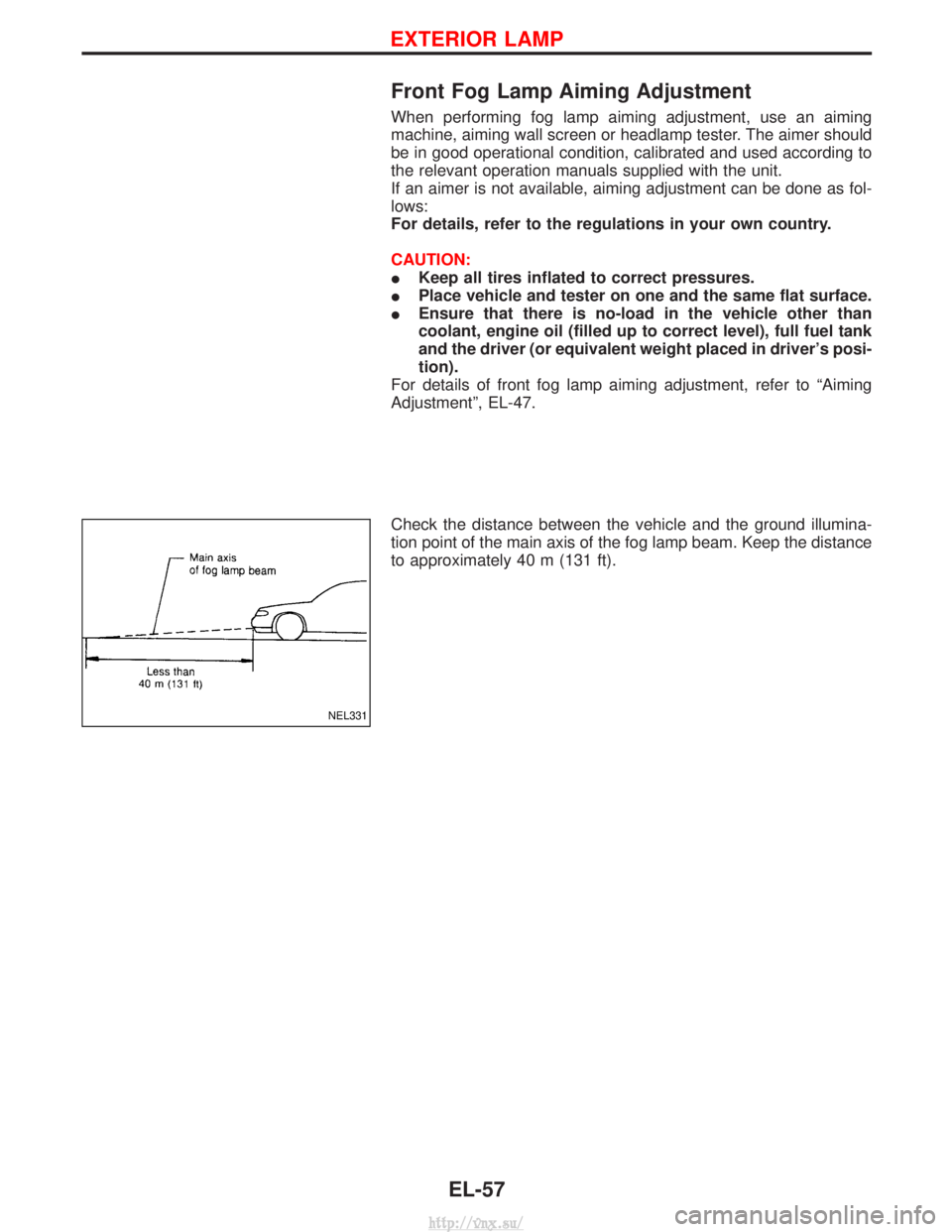
Check the distance between the vehicle and the ground illumina-
tion point of the main axis of the fog lamp beam. Keep the distance
to approximately 40 m (131 ft).
NEL331
EXTERIOR LAMP
EL-57
http://vnx.su/
Page 1830 of 1833
INT/V - Wiring diagram ................................EC-282
Intake air control valve control solenoidvalve .........................................................EC-281
Intake Air Volume .........................................EC-150
Intake door control linkage adjustment ..........HA-63
Intake manifold...............................................EM-12
Interior .............................................................BT-18
Interior lamp ..............................................EL-67, 74
Interior lamp on-off control..............................EL-73
ISO 15031-2 Terminology................................GI-34
K
Knuckle spindle ...............................................FA-20 L
License lamp ...................................................EL-49
Limited slip diff. adjustment............................PD-45
Limited slip diff. assembly ..............................PD-47
Limited slip diff. disassembly ...................PD-43, 44
Limited slip diff. inspection .............................PD-44
Line pressure solenoid valve ..........................AT-86
Line pressure test (A/T) ..........................AT-30, 201
Liquid gasket application .................................EM-3
Location of electrical units ............EL-275, 276, 278
Lock, door ...........................................BT-10, 12, 14
Low and reverse brake .................................AT-166
LSV (Load sensing valve) ..............................BR-10
Lubricants.......................................................MA-17
Lubrication circuit (engine) .........................LC-3, 20
Lubrication oil A/C (checking andadjusting) ....................................................HA-22
Lubrication oil A/C (SDS) ...............................HA-64
Lubrication-locks, hinges and hood latches ..................................................MA-36, 45
Luggage compartment trim .............................BT-18
M
MAFS - Wiring diagram..................................EC-90
MAIN - Wiring diagram...................................EC-80
Main drive gear (M/T) .....................................MT-11
Main gear (Transfer) .................................TF-10, 21
Mainshaft (M/T) ..............................................MT-11
Mainshaft (Transfer)..................................TF-10, 17
Maintenance ...........MA-5, 8, 11, 14, 20, 36, 48, 49
MAJOR OVERHALL .....................................AT-124
Major overhaul (Transfer) .................................TF-9
Malfunction indicator (MI).......................EC-34, 345
Manifold tightening torque (intake &exhaust) ...............................................MA-20, 28
Manual transmission number ..........................GI-29
Manual transmission oil replacement ......MA-36, 37
Map lamp ........................................................EL-74
Mass air flow sensor (MAFS) ................EC-88, 379
Master cylinder (brake) ..................................BR-17 Meter .........................................................EL-82, 85
METER - Wiring diagram................................EL-86
MIL/DL - Wiring diagram ..............................EC-310
MIRROR - Wiring diagram............................EL-154
Mirror, door......................................................BT-48
Model variation ................................................GI-27
Molding - See Exterior ....................................BT-21
M/T major overhaul ........................................MT-10
M/T removal and installation ........................MT-7, 8
Mud guard - See Exterior ...............................BT-21
MULTI - Wiring diagram................................EL-205
Multi-remote control
system ..............................EL-202, 204, 213, 215
Multiport fuel injection precautions ....................GI-5
N
NATS (Nissan anti-theftsystem) .....................EL-222, 223, 224, 231, 242
NATS - Wiring diagram .................................EL-225
NATS V2.0 precautions (For Europe) ...............GI-4
Needle lift sensor .........................................EC-450
NVH troubleshooting (EM) ...............................EM-8
O
Oil change (capacity) ............MA-21, 29, 37, 38, 39
Oil change (interval) ..................................MA-5, 35
Oil cooler (engine) ............................................LC-8
Oil pan (engine) .............................................EM-22
Oil pump (A/T)...............................................AT-139
Oil seal replacement (engine)........................EM-50
Oil seal replacement (front final drive4WD)...........................................................PD-10
OILPSW - Wiring diagram............................EC-474
On board diagnostic system ..................EC-33, 344
Overdrive control switch................................AT-100
Overheat .......................................................EC-109
Overrun clutch solenoid valve ..................AT-71, 72
Oversize piston ..............................................EM-74
P
Park/Neutral position switch .........................EC-256
Park/neutral position switch (A/T) ...........AT-93, 119
Parking drum brake ........................................BR-36
Parking lamp ...................................................EL-49
PCV (positive crankcase ventilation) .....EC-23, 335
Periodic maintenance ......................................MA-5
Piston pin inspection ......................................EM-71
Piston ring inspection.....................................EM-72
PNP/SW - Wiring diagram ...........................EC-257
POWER - Wiring diagram...............................EL-10
Power doorlock ...........EL-163, 164, 171, 179, 180, 182, 192
Power steering fluid level...............MA-36, 44, ST-4
Power steering gear .................................ST-12, 22
ALPHABETICAL INDEX
IDX-5
http://vnx.su/
Page 1831 of 1833
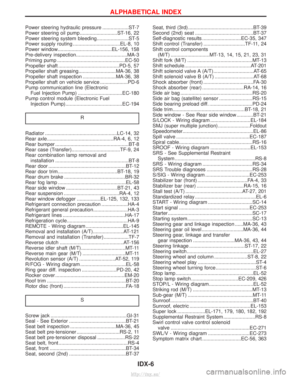
Power steering hydraulic pressure ...................ST-7
Power steering oil pump ...........................ST-16, 22
Power steering system bleeding.......................ST-5
Power supply routing ..................................EL-8, 10
Power window.......................................EL-156, 158
Pre-delivery inspection.....................................MA-3
Priming pump .................................................EC-50
Propeller shaft ............................................PD-5, 57
Propeller shaft greasing...........................MA-36, 38
Propeller shaft inspection ........................MA-36, 38
Propeller shaft on vehicle service ....................PD-6
Pump communication line (ElectronicFuel Injection Pump) ................................EC-180
Pump control module (Electronic Fuel Injection Pump).........................................EC-194
R
Radiator ....................................................LC-14, 32
Rear axle................................................RA-4, 6, 12
Rear bumper .....................................................BT-8
Rear case (Transfer)...................................TF-9, 24
Rear combination lamp removal andinstallation .....................................................BT-8
Rear door ........................................................BT-12
Rear door trim...........................................BT-18, 19
Rear drum brake ............................................BR-32
Rear fog lamp .................................................EL-58
Rear side window .....................................BT-21, 43
Rear suspension ........................................RA-4, 12
Rear window defogger .................EL-125, 132, 133
Refrigerant connection precaution ...................HA-4
Refrigerant general precaution.........................HA-3
Refrigerant lines .............................................HA-17
Refrigeration cycle............................................HA-9
REMOTE - Wiring diagram ...........................EL-145
Removal and installation (A/T)......................AT-121
Removal and installation (Transfer) ..................TF-7
Reverse clutch ..............................................AT-156
Reverse idler shaft (M/T)................................MT-11
Reverse main gear (M/T) ...............................MT-11
Revolution sensor (A/T) ..........................AT-52, 119
R/FOG - Wiring diagram .................................EL-58
Ring gear diff. inspection .........................PD-20, 42
Rocker cover ..................................................EM-20
Roof trim .........................................................BT-20
Rotor disc (front) .............................................FA-18
S
Screw jack .......................................................GI-31
Seal - See Exterior .........................................BT-21
Seat belt inspection .................................MA-36, 45
Seat belt pre-tensioner ...............................RS-2, 11
Seat belt pre-tensioner disposal ....................RS-22
Seat belt, front ..................................................RS-4
Seat, front .......................................................BT-34
Seat, second (2nd) .........................................BT-37 Seat, third (3rd) ...............................................BT-39
Second (2nd) seat ..........................................BT-37
Self-diagnostic results ............................EC-35, 347
Shift control (Transfer) ..............................TF-11, 24
Shift control components
(M/T) ............................MT-13, 14, 15, 21, 23, 31
Shift fork (M/T) ...............................................MT-13
Shift schedule................................................AT-201
Shift solenoid valve A (A/T).............................AT-65
Shift solenoid valve B (A/T) ............................AT-68
Shock absorber (front) ....................................FA-30
Shock absorber (rear) ..............................RA-14, 16
Side air bag ....................................................RS-20
Side air bag (satellite) sensor ........................RS-15
Side bearing preload diff. ...............................PD-24
Side trim....................................................BT-18, 21
Side window - See Rear side window ............BT-21
S/LOCK - Wiring diagram .............................EL-184
SMJ (super multiple junction) .......................Foldout
Speedometer...................................................EL-86
Spill valve .....................................................EC-187
Spiral cable.....................................................RS-16
SROOF - Wiring diagram .............................EL-153
SRS - See Supplemental Restraint System ..........................................................RS-8
SRS - Wiring diagram ....................................RS-34
SRS Trouble diagnoses .................................RS-28
S/SIG - Wiring diagram ................................EC-253
Stabilizer bar (front) ....................................FA-4, 33
Stabilizer bar (rear) ..................................RA-15, 16
Stall test (A/T) .........................................AT-27, 201
Standardized relay ............................................EL-6
START - Wiring diagram ................................SC-14
Start signal ...................................................EC-253
Starter .............................................................SC-17
Starting system...............................................SC-13
Steering gear and linkage inspection ......MA-36, 43
Steering gear oil level ..............................MA-36, 44
Steering gear, linkage and transfer gear inspection ..............................MA-36, 43, 44
Steering linkage ........................................ST-17, 22
Steering switch................................................EL-27
Steering wheel and column ........................ST-8, 22
Steering wheel play ..........................................ST-4
Steering wheel turning force .............................ST-6
Stop lamp ........................................................EL-52
Stop lamp switch ..................................EC-209, 426
STOP/L - Wiring diagram................................EL-52
Striking rod (M/T) ...........................................MT-13
Sub-gear (M/T) ...............................................MT-11
Sunroof............................................................BT-40
Sunroof, electric ............................................EL-153
Super lock ....................EL-171, 179, 180, 182, 192
Supplemental Restraint System .......................RS-8
Swirl control valve control solenoid valve .........................................................EC-271
SWL/V - Wiring diagram ..............................EC-273
Symptom matrix chart ............................EC-56, 363
ALPHABETICAL INDEX
IDX-6
http://vnx.su/