2004 NISSAN TERRANO oil level
[x] Cancel search: oil levelPage 918 of 1833
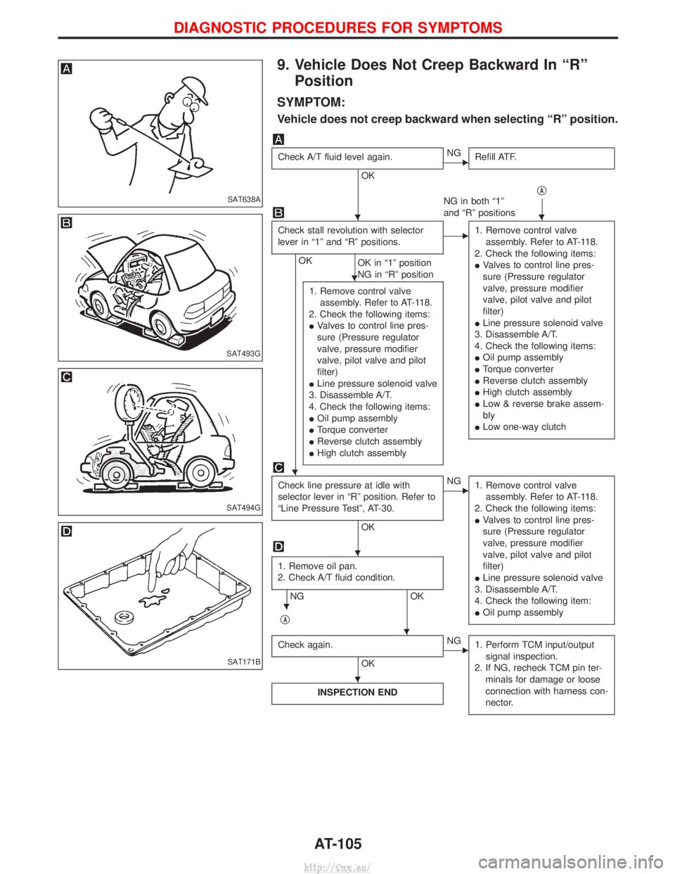
9. Vehicle Does Not Creep Backward In ªRºPosition
SYMPTOM:
Vehicle does not creep backward when selecting ªRº position.
Check A/T fluid level again.
OK
ENG Refill ATF.
qA
NG in both ª1º
and ªRº positions
Check stall revolution with selector
lever in ª1º and ªRº positions.
OK OK in ª1º position
NG in ªRº position
E1. Remove control valve
assembly. Refer to AT-118.
2. Check the following items:
I Valves to control line pres-
sure (Pressure regulator
valve, pressure modifier
valve, pilot valve and pilot
filter)
I Line pressure solenoid valve
3. Disassemble A/T.
4. Check the following items:
I Oil pump assembly
I Torque converter
I Reverse clutch assembly
I High clutch assembly
I Low & reverse brake assem-
bly
I Low one-way clutch
1. Remove control valve
assembly. Refer to AT-118.
2. Check the following items:
I Valves to control line pres-
sure (Pressure regulator
valve, pressure modifier
valve, pilot valve and pilot
filter)
I Line pressure solenoid valve
3. Disassemble A/T.
4. Check the following items:
I Oil pump assembly
I Torque converter
I Reverse clutch assembly
I High clutch assembly
Check line pressure at idle with
selector lever in ªRº position. Refer to
ªLine Pressure Testº, AT-30.
OK
ENG
1. Remove control valve
assembly. Refer to AT-118.
2. Check the following items:
I Valves to control line pres-
sure (Pressure regulator
valve, pressure modifier
valve, pilot valve and pilot
filter)
I Line pressure solenoid valve
3. Disassemble A/T.
4. Check the following item:
I Oil pump assembly
1. Remove oil pan.
2. Check A/T fluid condition.
NG OK
q
A
Check again.
OK
ENG 1. Perform TCM input/output
signal inspection.
2. If NG, recheck TCM pin ter- minals for damage or loose
connection with harness con-
nector.
INSPECTION END
SAT638A
SAT493G
SAT494G
SAT171B
HH
H
H
H
H
H
H
DIAGNOSTIC PROCEDURES FOR SYMPTOMS
AT-105
http://vnx.su/
Page 919 of 1833
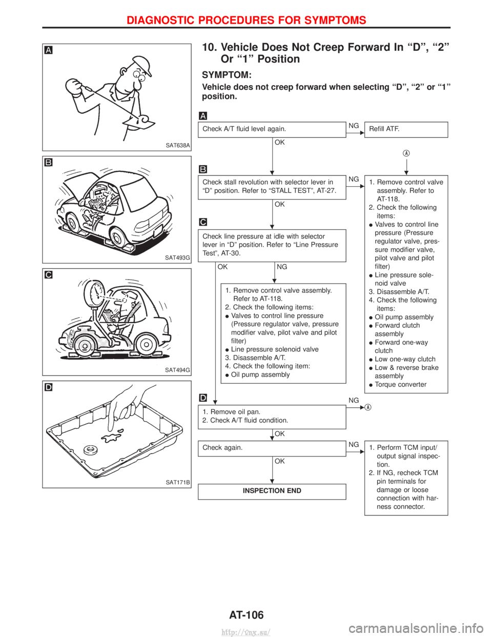
10. Vehicle Does Not Creep Forward In ªDº, ª2ºOr ª1º Position
SYMPTOM:
Vehicle does not creep forward when selecting ªDº, ª2º or ª1º
position.
Check A/T fluid level again.
OK
ENG Refill ATF.
qA
Check stall revolution with selector lever in
ªDº position. Refer to ªSTALL TESTº, AT-27.
OK
ENG1. Remove control valve
assembly. Refer to
AT-118.
2. Check the following items:
I Valves to control line
pressure (Pressure
regulator valve, pres-
sure modifier valve,
pilot valve and pilot
filter)
I Line pressure sole-
noid valve
3. Disassemble A/T.
4. Check the following items:
I Oil pump assembly
I Forward clutch
assembly
I Forward one-way
clutch
I Low one-way clutch
I Low & reverse brake
assembly
I Torque converter
Check line pressure at idle with selector
lever in ªDº position. Refer to ªLine Pressure
Testº, AT-30.
OK NG
1. Remove control valve assembly. Refer to AT-118.
2. Check the following items:
I Valves to control line pressure
(Pressure regulator valve, pressure
modifier valve, pilot valve and pilot
filter)
I Line pressure solenoid valve
3. Disassemble A/T.
4. Check the following item:
I Oil pump assembly
1. Remove oil pan.
2. Check A/T fluid condition.
OK
ENG qA
Check again.
OK
ENG 1. Perform TCM input/
output signal inspec-
tion.
2. If NG, recheck TCM pin terminals for
damage or loose
connection with har-
ness connector.
INSPECTION END
SAT638A
SAT493G
SAT494G
SAT171B
HH
H
H
H
HH
H
DIAGNOSTIC PROCEDURES FOR SYMPTOMS
AT-106
http://vnx.su/
Page 1078 of 1833
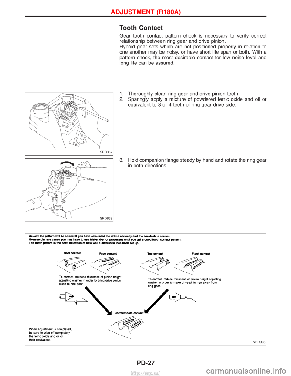
Tooth Contact
Gear tooth contact pattern check is necessary to verify correct
relationship between ring gear and drive pinion.
Hypoid gear sets which are not positioned properly in relation to
one another may be noisy, or have short life span or both. With a
pattern check, the most desirable contact for low noise level and
long life can be assured.
1. Thoroughly clean ring gear and drive pinion teeth.
2. Sparingly apply a mixture of powdered ferric oxide and oil orequivalent to 3 or 4 teeth of ring gear drive side.
3. Hold companion flange steady by hand and rotate the ring gear in both directions.
SPD357
SPD653
NPD003
ADJUSTMENT (R180A)
PD-27
http://vnx.su/
Page 1103 of 1833
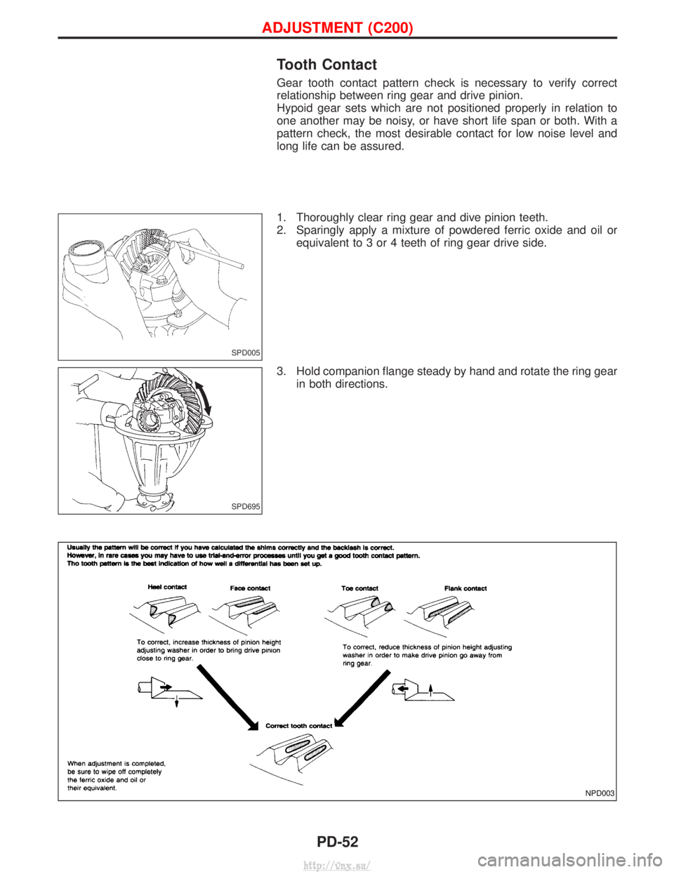
Tooth Contact
Gear tooth contact pattern check is necessary to verify correct
relationship between ring gear and drive pinion.
Hypoid gear sets which are not positioned properly in relation to
one another may be noisy, or have short life span or both. With a
pattern check, the most desirable contact for low noise level and
long life can be assured.
1. Thoroughly clear ring gear and dive pinion teeth.
2. Sparingly apply a mixture of powdered ferric oxide and oil orequivalent to 3 or 4 teeth of ring gear drive side.
3. Hold companion flange steady by hand and rotate the ring gear in both directions.
SPD005
SPD695
NPD003
ADJUSTMENT (C200)
PD-52
http://vnx.su/
Page 1172 of 1833
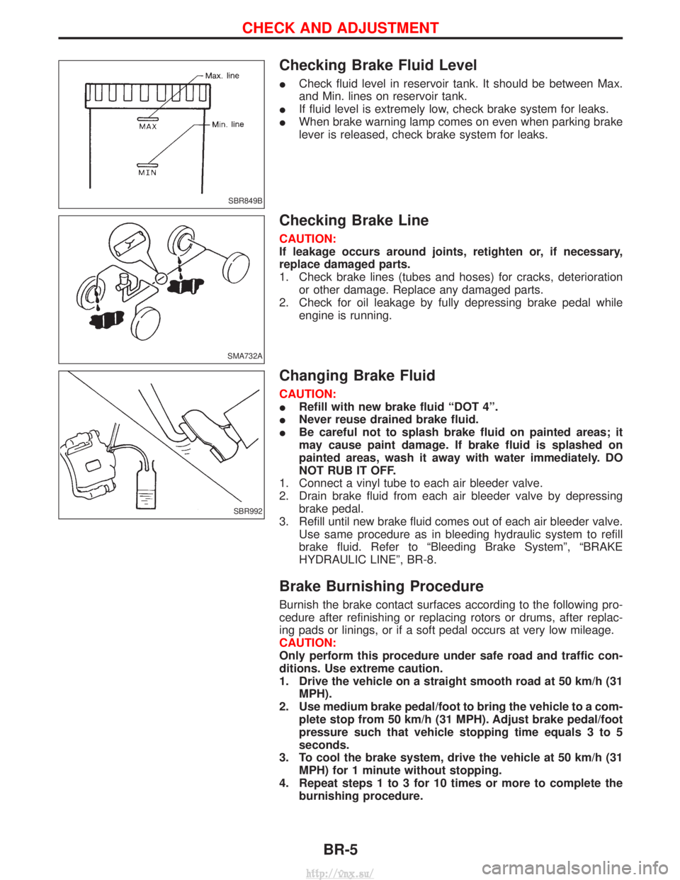
Checking Brake Fluid Level
ICheck fluid level in reservoir tank. It should be between Max.
and Min. lines on reservoir tank.
I If fluid level is extremely low, check brake system for leaks.
I When brake warning lamp comes on even when parking brake
lever is released, check brake system for leaks.
Checking Brake Line
CAUTION:
If leakage occurs around joints, retighten or, if necessary,
replace damaged parts.
1. Check brake lines (tubes and hoses) for cracks, deterioration
or other damage. Replace any damaged parts.
2. Check for oil leakage by fully depressing brake pedal while engine is running.
Changing Brake Fluid
CAUTION:
IRefill with new brake fluid ªDOT 4º.
I Never reuse drained brake fluid.
I Be careful not to splash brake fluid on painted areas; it
may cause paint damage. If brake fluid is splashed on
painted areas, wash it away with water immediately. DO
NOT RUB IT OFF.
1. Connect a vinyl tube to each air bleeder valve.
2. Drain brake fluid from each air bleeder valve by depressing brake pedal.
3. Refill until new brake fluid comes out of each air bleeder valve. Use same procedure as in bleeding hydraulic system to refill
brake fluid. Refer to ªBleeding Brake Systemº, ªBRAKE
HYDRAULIC LINEº, BR-8.
Brake Burnishing Procedure
Burnish the brake contact surfaces according to the following pro-
cedure after refinishing or replacing rotors or drums, after replac-
ing pads or linings, or if a soft pedal occurs at very low mileage.
CAUTION:
Only perform this procedure under safe road and traffic con-
ditions. Use extreme caution.
1. Drive the vehicle on a straight smooth road at 50 km/h (31MPH).
2. Use medium brake pedal/foot to bring the vehicle to a com- plete stop from 50 km/h (31 MPH). Adjust brake pedal/foot
pressure such that vehicle stopping time equals 3 to 5
seconds.
3. To cool the brake system, drive the vehicle at 50 km/h (31 MPH) for 1 minute without stopping.
4. Repeat steps 1 to 3 for 10 times or more to complete the burnishing procedure.
SBR849B
SMA732A
SBR992
CHECK AND ADJUSTMENT
BR-5
http://vnx.su/
Page 1254 of 1833
STEERING SYSTEM
SECTION
ST
CONTENTS
PRECAUTIONS ...............................................................2
Supplemental Restraint System (SRS) ²AIR
BAG² and²SEAT BELT PRE-TENSIONER² ...............2
Precautions for SRS ²AIR BAG² and²SEAT
BELT PRE-TENSIONER² Service ...............................2
Precautions for Steering System .................................2
PREPARATION ................................................................3
Special Service Tools ..................................................3
ON-VEHICLE SERVICE ..................................................4
Checking Steering Wheel Play ....................................4
Checking Neutral Position on Steering Wheel ............4
Front Wheel Turning Angle ..........................................4
Checking and Adjusting Drive Belts ............................4
Checking Fluid Level ...................................................4
Checking Fluid Leakage ..............................................5
Bleeding Hydraulic System..........................................5
Checking Steering Wheel Turning Force ....................6
Checking Hydraulic System.........................................7 STEERING WHEEL AND STEERING COLUMN
............8
Removal and Installation .............................................8
Disassembly and Assembly .......................................10
Inspection................................................................... 11
POWER STEERING GEAR ...........................................12
Description .................................................................12
Removal and Installation ...........................................14
Inspection and Adjustment ........................................15
POWER STEERING OIL PUMP ....................................16
Removal and Installation ...........................................16
STEERING LINKAGE ....................................................17
Removal and Installation ...........................................17
Disassembly and Assembly .......................................19
Inspection...................................................................20
SERVICE DATA AND SPECIFICATIONS (SDS) ..........22
General Specifications ...............................................22
Inspection and Adjustment ........................................22
http://vnx.su/
Page 1258 of 1833
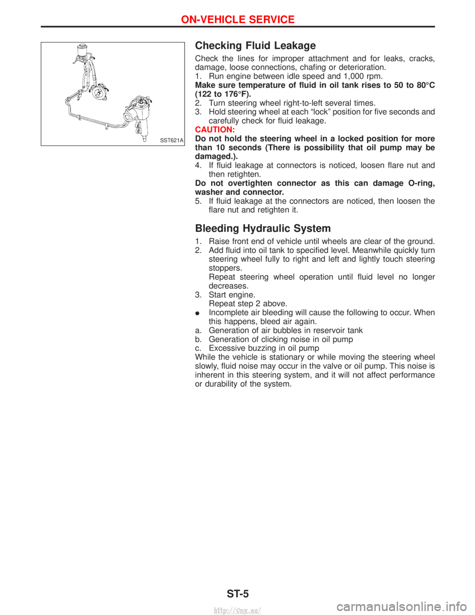
Checking Fluid Leakage
Check the lines for improper attachment and for leaks, cracks,
damage, loose connections, chafing or deterioration.
1. Run engine between idle speed and 1,000 rpm.
Make sure temperature of fluid in oil tank rises to 50 to 80ÉC
(122 to 176ÉF).
2. Turn steering wheel right-to-left several times.
3. Hold steering wheel at each ªlockº position for five seconds andcarefully check for fluid leakage.
CAUTION:
Do not hold the steering wheel in a locked position for more
than 10 seconds (There is possibility that oil pump may be
damaged.).
4. If fluid leakage at connectors is noticed, loosen flare nut and then retighten.
Do not overtighten connector as this can damage O-ring,
washer and connector.
5. If fluid leakage at the connectors are noticed, then loosen the flare nut and retighten it.
Bleeding Hydraulic System
1. Raise front end of vehicle until wheels are clear of the ground.
2. Add fluid into oil tank to specified level. Meanwhile quickly turnsteering wheel fully to right and left and lightly touch steering
stoppers.
Repeat steering wheel operation until fluid level no longer
decreases.
3. Start engine. Repeat step 2 above.
I Incomplete air bleeding will cause the following to occur. When
this happens, bleed air again.
a. Generation of air bubbles in reservoir tank
b. Generation of clicking noise in oil pump
c. Excessive buzzing in oil pump
While the vehicle is stationary or while moving the steering wheel
slowly, fluid noise may occur in the valve or oil pump. This noise is
inherent in this steering system, and it will not affect performance
or durability of the system.
SST621A
ON-VEHICLE SERVICE
ST-5
http://vnx.su/
Page 1259 of 1833
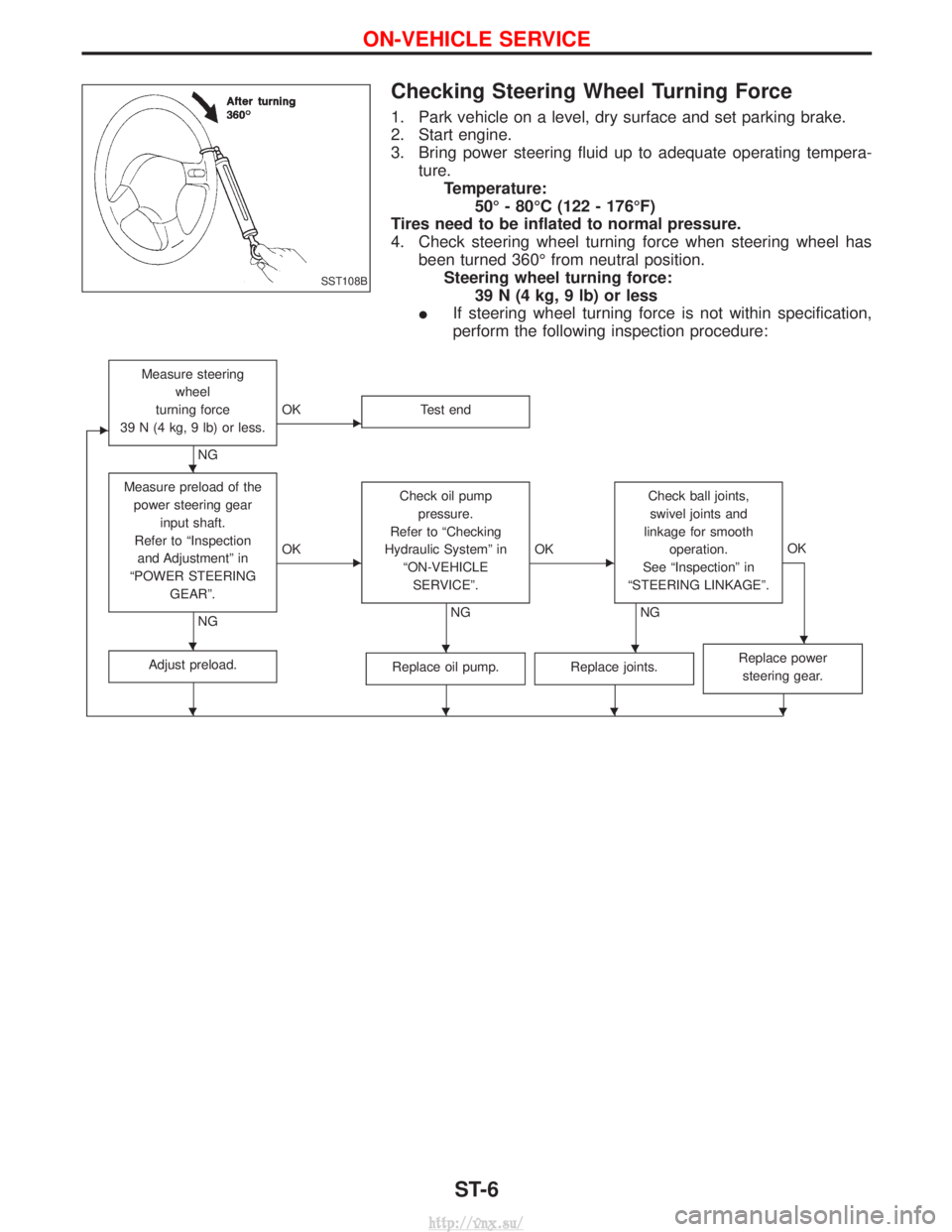
Checking Steering Wheel Turning Force
1. Park vehicle on a level, dry surface and set parking brake.
2. Start engine.
3. Bring power steering fluid up to adequate operating tempera-ture.Temperature: 50É - 80ÉC (122 - 176ÉF)
Tires need to be inflated to normal pressure.
4. Check steering wheel turning force when steering wheel has been turned 360É from neutral position.Steering wheel turning force: 39 N (4 kg, 9 lb) or less
I If steering wheel turning force is not within specification,
perform the following inspection procedure:
E
Measure steering
wheel
turning force
39 N (4 kg, 9 lb) or less.
NG
EOK Test end
Measure preload of the
power steering gear input shaft.
Refer to ªInspection and Adjustmentº in
ªPOWER STEERING GEARº.
NG
EOK Check oil pump
pressure.
Refer to ªChecking
Hydraulic Systemº in ªON-VEHICLESERVICEº.
NG
EOK Check ball joints,
swivel joints and
linkage for smooth operation.
See ªInspectionº in
ªSTEERING LINKAGEº.
NG OK
Adjust preload.Replace oil pump.Replace joints.Replace power
steering gear.
SST108B
H
HHHH
HHHH
ON-VEHICLE SERVICE
ST-6
http://vnx.su/