2004 NISSAN TERRANO oil level
[x] Cancel search: oil levelPage 108 of 1833
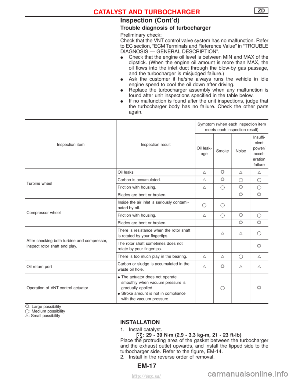
Trouble diagnosis of turbocharger
Preliminary check:
Check that the VNT control valve system has no malfunction. Refer
to EC section, ªECM Terminals and Reference Valueº in ªTROUBLE
DIAGNOSIS Ð GENERAL DESCRIPTIONº.
ICheck that the engine oil level is between MIN and MAX of the
dipstick. (When the engine oil amount is more than MAX, the
oil flows into the inlet duct through the blow-by gas passage,
and the turbocharger is misjudged failure.)
I Ask the customer if he/she always runs the vehicle in idle
engine speed to cool the oil down after driving.
I Replace the turbocharger assembly when any malfunction is
found after unit inspections specified in the table below.
I If no malfunction is found after the unit inspections, judge that
the turbocharger body has no failure. Check the other parts
again.
Inspection item Inspection resultSymptom (when each inspection item
meets each inspection result)
Oil leak- age Smoke Noise Insuffi-
cient
power/ accel-
eration failure
Turbine wheel Oil leaks.
g
gg
Carbon is accumulated. g
qq
Friction with housing. gq
q
Blades are bent or broken.
Compressor wheel Inside the air inlet is seriously contami-
nated by oil.
qq
Friction with housing. gqq
Blades are bent or broken.
After checking both turbine and compressor,
inspect rotor shaft end play. There is resistance when the rotor shaft
is rotated by your fingertips.
ggq
The rotor shaft sometimes does not
rotate by your fingertips.
There is too much play in the bearing. g gqg
Oil return port Carbon or sludge is accumulated in the
waste oil hole.g
gg
Operation of VNT control actuator I
The actuator does not operate
smoothly when vacuum pressure is
gradually applied.
I Stroke amount is not in compliance
with the vacuum pressure. q
: Large possibility
q: Medium possibility
g: Small possibility
INSTALLATION
1. Install catalyst.
:29-39N ×m (2.9 - 3.3 kg-m, 21 - 23 ft-lb)
Place the protruding area of the gasket between the turbocharger
and the exhaust outlet upwards, and install the lipped side to the
turbocharger side. Refer to the figure, EM-14.
2. Install in the reverse order of removal.
CATALYST AND TURBOCHARGERZD
Inspection (Cont'd)
EM-17
http://vnx.su/
Page 155 of 1833

Engine room (Left)
3. Remove air duct and air cleaner case.
4. Disconnect vacuum hose to the vehicle on the engine.
5. Disconnect harness connectors from alternator and air com-pressor.
6. Remove alternator.
7. After removing refrigerant, remove pipes of air compressor and inlet/outlet.
8. Disconnect heating hose, install blank cap to hose to prevent coolant from leaking.
9. Remove heating pipe.
10. Remove heat insulator.
11. Remove catalytic converter.
Engine room (Right)
12. Remove power steering reservoir tank from bracket, and fix it to the vehicle with a rope.
CAUTION:
Keep the reservoir tank level when fixing to prevent oil leak.
13. Remove fuel feed and return hoses.
CAUTION:
Install blank caps immediately to avoid fuel leakage.
14. Remove all harness connectors on the engine, and move har- nesses to the side of the vehicle.
Vehicle underfloor
15. Remove starter motor.
16. Detach A/T oil cooler pipes from oil pan. (A/T model)
17. Remove rear propeller shaft.
18. Remove mounting bolts to secure the engine to transmission.
1) Remove torque converter installation bolt. (A/T model)
2) Lift transmission bottom with transmission jack, and removerear mount members from the vehicle.
3) Lower transmission with the jack, and remove upper mounting bolts securing the engine to transmission.
4) Lift transmission with the jack, and reinstall rear mount mem- bers to the vehicle.
5) Position the jack to the front side of transmission.
6) Remove remaining mounting bolts securing the engine to trans- mission.
Removal operation
19. Remove air conditioner high pressure pipes at the rear of theengine room.
I This is due to some inconvenience in the rear slinger installa-
tion.
20. Install the engine slingers (standard service part) to front-left and rear-right.
:25-28N ×m (2.5 - 2.9 kg-m, 18 - 20 ft-lb)
WARNING:
For engines without engine slingers, attach proper slingers
and bolts described in the PARTS CATALOG.
FEM082
ENGINE REMOVALZD
Removal (Cont'd)
EM-64
http://vnx.su/
Page 156 of 1833
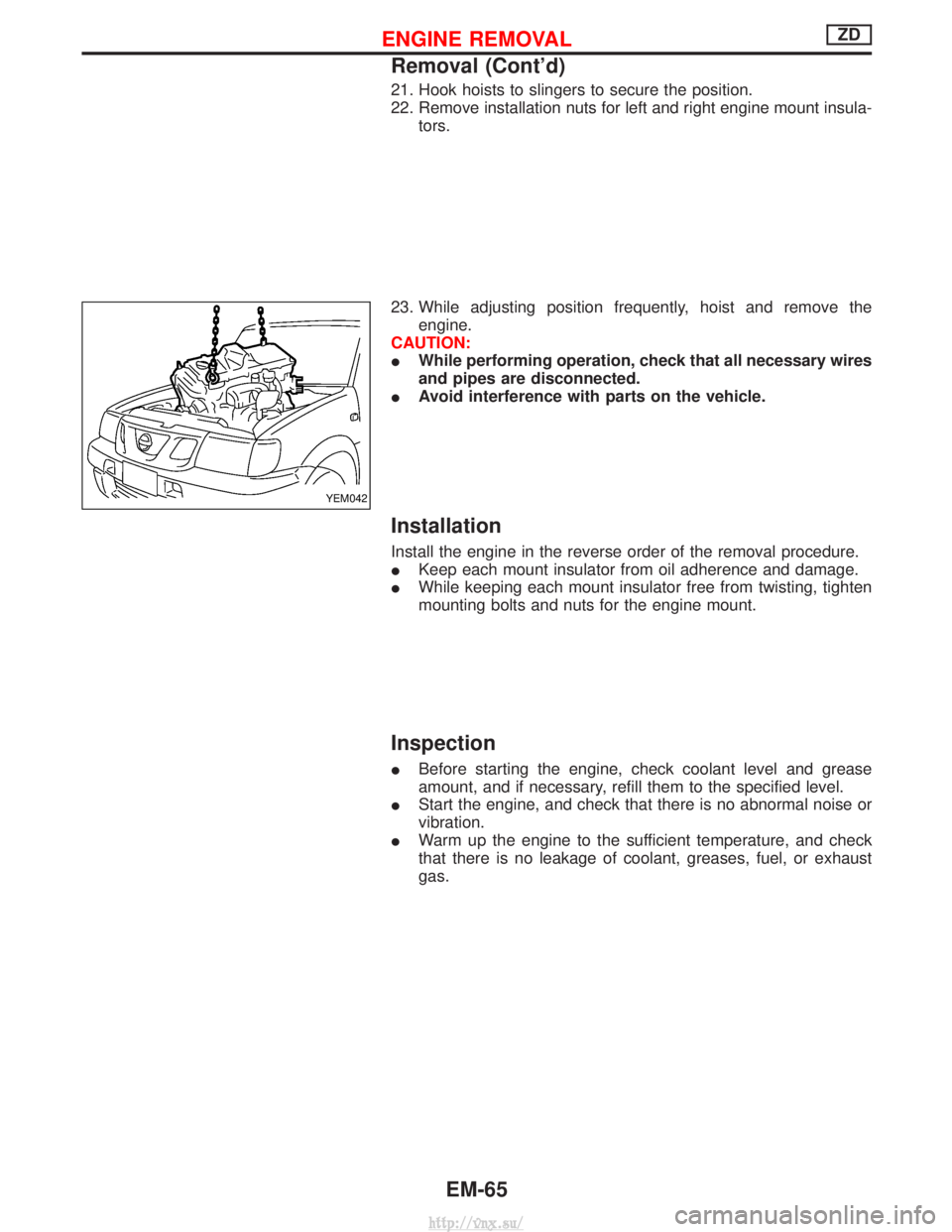
21. Hook hoists to slingers to secure the position.
22. Remove installation nuts for left and right engine mount insula-tors.
23. While adjusting position frequently, hoist and remove the engine.
CAUTION:
I While performing operation, check that all necessary wires
and pipes are disconnected.
I Avoid interference with parts on the vehicle.
Installation
Install the engine in the reverse order of the removal procedure.
IKeep each mount insulator from oil adherence and damage.
I While keeping each mount insulator free from twisting, tighten
mounting bolts and nuts for the engine mount.
Inspection
IBefore starting the engine, check coolant level and grease
amount, and if necessary, refill them to the specified level.
I Start the engine, and check that there is no abnormal noise or
vibration.
I Warm up the engine to the sufficient temperature, and check
that there is no leakage of coolant, greases, fuel, or exhaust
gas.
YEM042
ENGINE REMOVALZD
Removal (Cont'd)
EM-65
http://vnx.su/
Page 245 of 1833
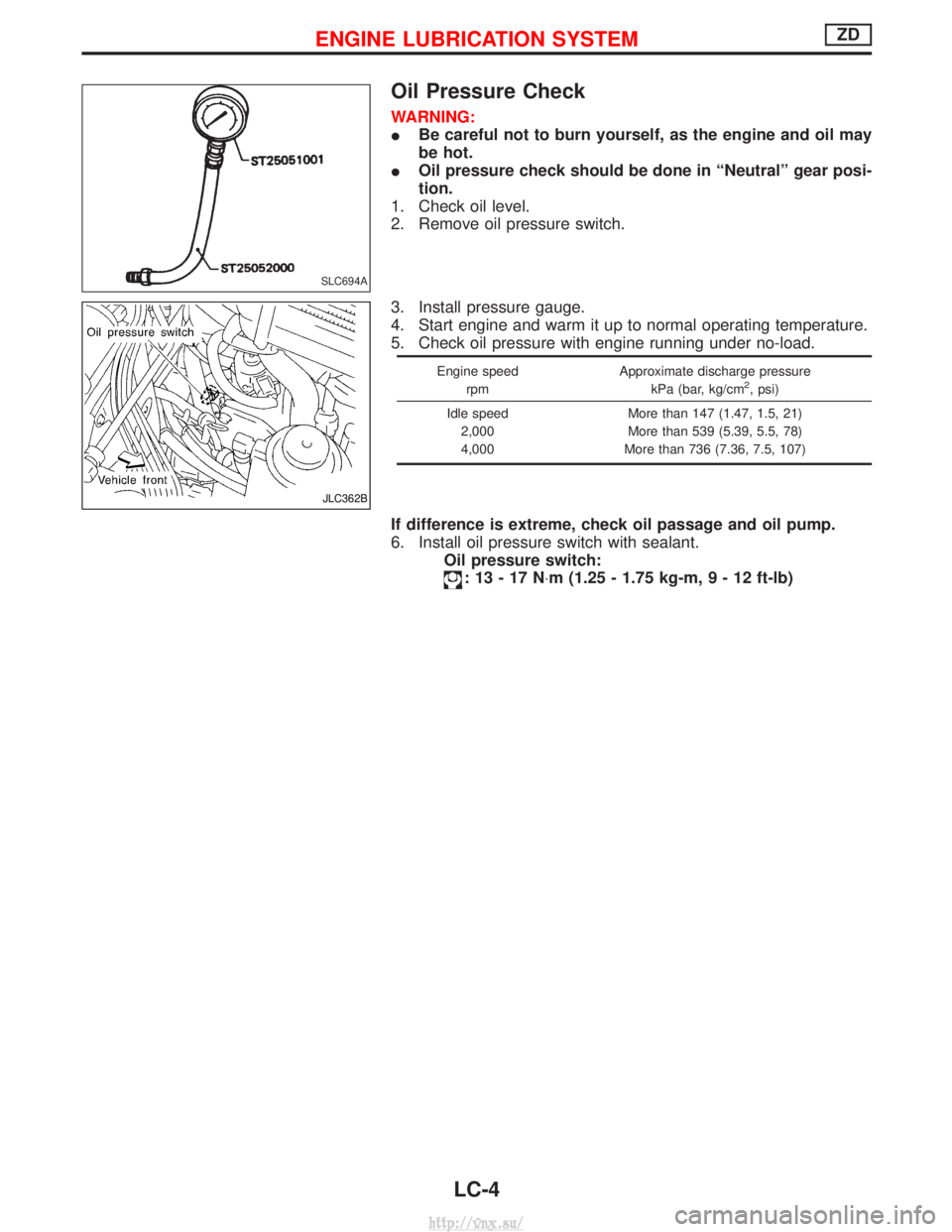
Oil Pressure Check
WARNING:
IBe careful not to burn yourself, as the engine and oil may
be hot.
I Oil pressure check should be done in ªNeutralº gear posi-
tion.
1. Check oil level.
2. Remove oil pressure switch.
3. Install pressure gauge.
4. Start engine and warm it up to normal operating temperature.
5. Check oil pressure with engine running under no-load.
Engine speed
rpm Approximate discharge pressure
kPa (bar, kg/cm2, psi)
Idle speed 2,000
4,000 More than 147 (1.47, 1.5, 21)
More than 539 (5.39, 5.5, 78)
More than 736 (7.36, 7.5, 107)
If difference is extreme, check oil passage and oil pump.
6. Install oil pressure switch with sealant. Oil pressure switch:
:13-17N ×m (1.25 - 1.75 kg-m ,9-12ft-lb)
SLC694A
JLC362B
ENGINE LUBRICATION SYSTEMZD
LC-4
http://vnx.su/
Page 262 of 1833
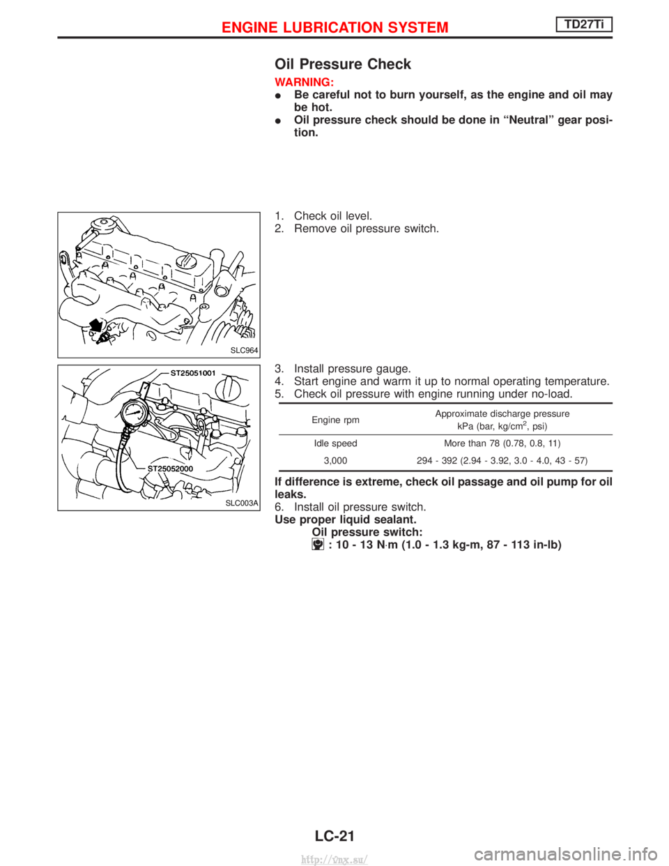
Oil Pressure Check
WARNING:
IBe careful not to burn yourself, as the engine and oil may
be hot.
I Oil pressure check should be done in ªNeutralº gear posi-
tion.
1. Check oil level.
2. Remove oil pressure switch.
3. Install pressure gauge.
4. Start engine and warm it up to normal operating temperature.
5. Check oil pressure with engine running under no-load.
Engine rpm Approximate discharge pressure
kPa (bar, kg/cm2, psi)
Idle speed More than 78 (0.78, 0.8, 11) 3,000 294 - 392 (2.94 - 3.92, 3.0 - 4.0, 43 - 57)
If difference is extreme, check oil passage and oil pump for oil
leaks.
6. Install oil pressure switch.
Use proper liquid sealant. Oil pressure switch:
:10-13N ×m (1.0 - 1.3 kg-m, 87 - 113 in-lb)
SLC964
SLC003A
ENGINE LUBRICATION SYSTEMTD27Ti
LC-21
http://vnx.su/
Page 303 of 1833
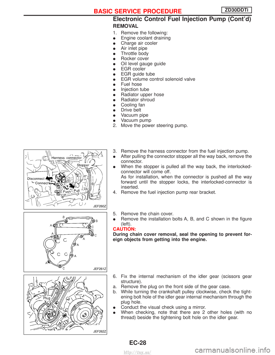
REMOVAL
1. Remove the following:
IEngine coolant draining
I Charge air cooler
I Air inlet pipe
I Throttle body
I Rocker cover
I Oil level gauge guide
I EGR cooler
I EGR guide tube
I EGR volume control solenoid valve
I Fuel hose
I Injection tube
I Radiator upper hose
I Radiator shroud
I Cooling fan
I Drive belt
I Vacuum pipe
I Vacuum pump
2. Move the power steering pump.
3. Remove the harness connector from the fuel injection pump.
I After pulling the connector stopper all the way back, remove the
connector.
I When the stopper is pulled all the way back, the interlocked-
connector will come off.
As for installation, when the connector is pushed all the way
forward until the stopper locks, the interlocked-connector is
inserted.
4. Remove the fuel injection pump rear bracket.
5. Remove the chain cover.
I Remove the installation bolts A, B, and C shown in the figure
(left).
CAUTION:
During chain cover removal, seal the opening to prevent for-
eign objects from getting into the engine.
6. Fix the internal mechanism of the idler gear (scissors gear structure).
a. Remove the plug on the front side of the gear case.
b. While turning the crankshaft pulley clockwise, check the tight- ening bolt hole of the idler gear internal mechanism through the
plug hole.
I Conduct the visual check using a mirror.
I When checking, note that there are 2 other holes (with no
thread) beside the tightening bolt hole on the idler gear.
JEF260Z
JEF261Z
JEF262Z
BASIC SERVICE PROCEDUREZD30DDTi
Electronic Control Fuel Injection Pump (Cont'd)
EC-28
http://vnx.su/
Page 385 of 1833
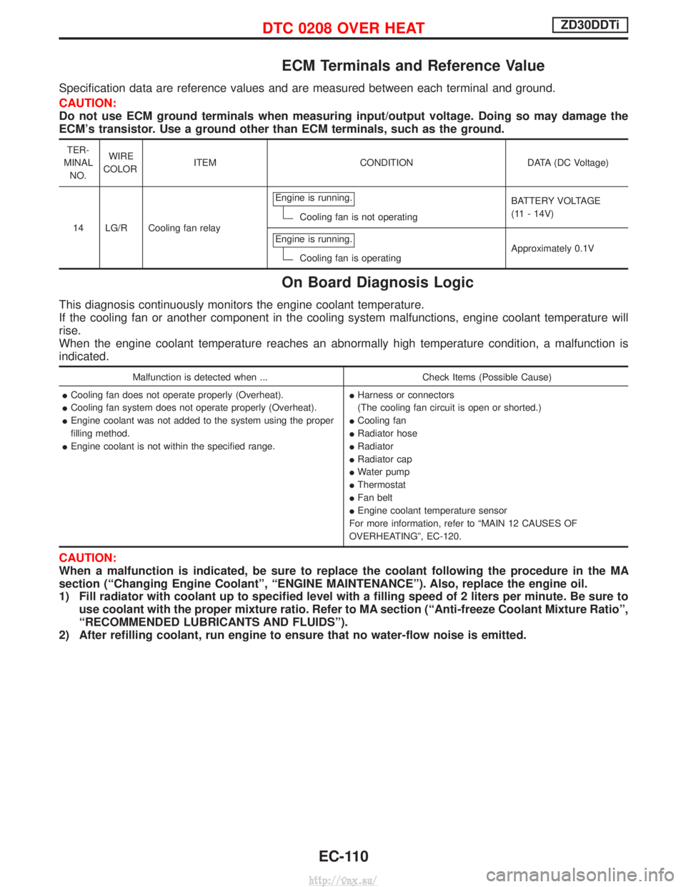
ECM Terminals and Reference Value
Specification data are reference values and are measured between each terminal and ground.
CAUTION:
Do not use ECM ground terminals when measuring input/output voltage. Doing so may damage the
ECM's transistor. Use a ground other than ECM terminals, such as the ground.
TER-
MINAL NO. WIRE
COLOR ITEM CONDITION DATA (DC Voltage)
14 LG/R Cooling fan relay Engine is running.
Cooling fan is not operating
BATTERY VOLTAGE
(11 - 14V)
Engine is running.
Cooling fan is operating Approximately 0.1V
On Board Diagnosis Logic
This diagnosis continuously monitors the engine coolant temperature.
If the cooling fan or another component in the cooling system malfunctions, engine coolant temperature will
rise.
When the engine coolant temperature reaches an abnormally high temperature condition, a malfunction is
indicated.
Malfunction is detected when ...
Check Items (Possible Cause)
I Cooling fan does not operate properly (Overheat).
I Cooling fan system does not operate properly (Overheat).
I Engine coolant was not added to the system using the proper
filling method.
I Engine coolant is not within the specified range. I
Harness or connectors
(The cooling fan circuit is open or shorted.)
I Cooling fan
I Radiator hose
I Radiator
I Radiator cap
I Water pump
I Thermostat
I Fan belt
I Engine coolant temperature sensor
For more information, refer to ªMAIN 12 CAUSES OF
OVERHEATINGº, EC-120.
CAUTION:
When a malfunction is indicated, be sure to replace the coolant following the procedure in the MA
section (ªChanging Engine Coolantº, ªENGINE MAINTENANCEº). Also, replace the engine oil.
1) Fill radiator with coolant up to specified level with a filling speed of 2 liters per minute. Be sure to use coolant with the proper mixture ratio. Refer to MA section (ªAnti-freeze Coolant Mixture Ratioº,
ªRECOMMENDED LUBRICANTS AND FLUIDSº).
2) After refilling coolant, run engine to ensure that no water-flow noise is emitted.
DTC 0208 OVER HEATZD30DDTi
EC-110
http://vnx.su/
Page 572 of 1833
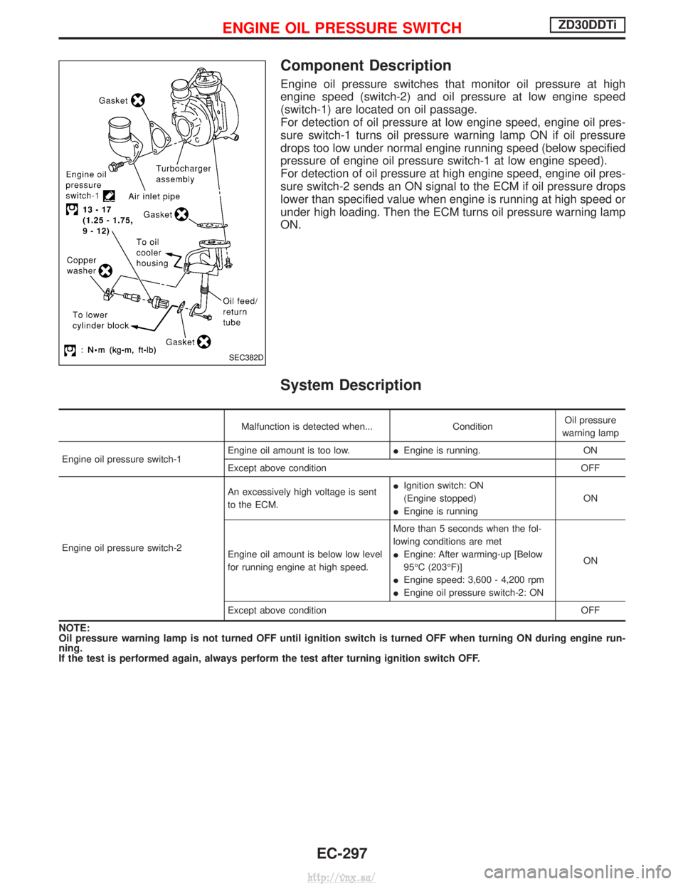
Component Description
Engine oil pressure switches that monitor oil pressure at high
engine speed (switch-2) and oil pressure at low engine speed
(switch-1) are located on oil passage.
For detection of oil pressure at low engine speed, engine oil pres-
sure switch-1 turns oil pressure warning lamp ON if oil pressure
drops too low under normal engine running speed (below specified
pressure of engine oil pressure switch-1 at low engine speed).
For detection of oil pressure at high engine speed, engine oil pres-
sure switch-2 sends an ON signal to the ECM if oil pressure drops
lower than specified value when engine is running at high speed or
under high loading. Then the ECM turns oil pressure warning lamp
ON.
System Description
Malfunction is detected when...ConditionOil pressure
warning lamp
Engine oil pressure switch-1 Engine oil amount is too low.
IEngine is running. ON
Except above condition OFF
Engine oil pressure switch-2 An excessively high voltage is sent
to the ECM.
I
Ignition switch: ON
(Engine stopped)
I Engine is running ON
Engine oil amount is below low level
for running engine at high speed. More than 5 seconds when the fol-
lowing conditions are met
I
Engine: After warming-up [Below
95ÉC (203ÉF)]
I Engine speed: 3,600 - 4,200 rpm
I Engine oil pressure switch-2: ON ON
Except above condition OFF
NOTE:
Oil pressure warning lamp is not turned OFF until ignition switch is turned OFF when turning ON during engine run-
ning.
If the test is performed again, always perform the test after turning ignition switch OFF.
SEC382D
ENGINE OIL PRESSURE SWITCHZD30DDTi
EC-297
http://vnx.su/