2004 MITSUBISHI ENDEAVOR belt
[x] Cancel search: beltPage 434 of 3870
next step. If DTC B1536 is not retrieved, an intermittent condition may exist.
3. Disconnect negative battery cable. Disconnect driver-side seat belt buckle
connector D-29. Latch seat belt into seat belt buckle. Measure resistance
between connector D-29, terminals No. 3 and 5. See Fig. 44
. Resistance
should be 800-840 ohms. Resistance between ground and terminals No. 3 and
5 should be infinite. Unlatch seat belt buckle. Measure resistance between
terminal No. 4 and 5 of connector D-29. Resistance should be 800-840 ohms.
Resistance between ground and terminals No. 4 and 5 should be infinite. If
resistance is as specified, go to next step. If resistance is not as specified,
replace front seat belt buckle.
4. Reconnect connector D-29. Disconnect SRS ECU connector C-40. See SRS
ELECTRONIC CONTROL UNIT (SRS ECU)
under REMOVAL &
INSTALLATION. See Fig. 30
. Latch driver seat belt buckle. Measure
resistance between SRS ECU connector C-40, terminals No. 3 (Blue/Yellow
wire) and No. 4 (Green wire). See Fig. 33
. Resistance should be 738-902
ohms. Unlatch driver seat belt buckle. Measure resistance between SRS ECU
connector C-40, terminal No. 4 (Green wire) and No. 18 (Violet wire).
Resistance should be 738-902 ohms. If resistance is not as specified, go to next
step. If resistance is a specified, erase, then retrieve DTCs. If DTC B1536 is
retrieved, replace SRS ECU. Go to step 6 .
5. Inspect wire harness between SRS ECU connector C-40 and driver seat belt
buckle connector D-29 for damage. If wires are okay, go to next step. If wires
are not okay, replace wire harness. Go to next step.
6. Erase, then retrieve DTCs. If DTC B1536 is retrieved, go to step 1 . If DTC
B1536 is not retrieved, system is normal at this time.
DTC B1537: SEAT BELT SWITCH (LH) CIRCUIT OPEN FOR COM TERMINAL 1. Connect scan tool to Data Link Connector (DLC). See INITIAL SRS
DIAGNOSTIC PROCEDURE
under DIAGNOSTICS. If scan tool is able to
diagnose CAN bus lines and CAN bus lines are satisfactory, go to next step. If
scan tool cannot diagnose CAN bus lines, repair CAN bus lines. Go to next
step.
2. Erase, then retrieve DTCs. Turn ignition off. If DTC B1537 is retrieved, go to
next ste
p. If DTC B1537 is not retrieved, an intermittent condition ma
y exist.
2004 Mitsubishi Endeavor Limited
2004 ACCESSORIES/SAFETY EQUIPMENT Mitsubishi - Air Bag Restraint Systems
Page 435 of 3870
3. Disconnect negative battery cable. Disconnect driver-side seat belt buckle
connector D-29. Latch seat belt into seat belt buckle. Measure resistance
between connector D-29, terminals No. 3 and 5. See Fig. 44
. Resistance
should be 800-840 ohms. Resistance between ground and terminals No. 3 and
5 should be infinite. Unlatch seat belt buckle. Measure resistance between
terminal No. 4 and 5 of connector D-29. Resistance should be 800-840 ohms.
Resistance between ground and terminals No. 4 and 5 should be infinite. If
resistance is as specified, go to next step. If resistance is not as specified,
replace front seat belt buckle.
4. Reconnect connector D-29. Disconnect SRS ECU connector C-40. See SRS
ELECTRONIC CONTROL UNIT (SRS ECU)
under REMOVAL &
INSTALLATION. See Fig. 30
. Latch driver seat belt buckle. Measure
resistance between SRS ECU connector C-40, terminal No. 3 (Blue/Yellow
wire) and No. 4 (Green wire). See Fig. 33
. Resistance should be 738-902
ohms. Unlatch driver seat belt buckle. Measure resistance between SRS ECU
connector C-40, terminal No. 4 (Green wire) and No. 18 (Violet wire).
Resistance should be 738-902 ohms. If resistance is not as specified, go to next
step. If resistance is a specified, erase, then retrieve DTCs. If DTC B1537 is
retrieved, replace SRS ECU. Go to step 6 .
5. Inspect wire harness between SRS ECU connector C-40 and driver seat belt
buckle connector D-29 for damage. If wires are okay, go to next step. If wires
are not okay, replace wire harness. Go to next step.
6. Erase, then retrieve DTCs. If DTC B1537 is retrieved, go to step 1 . If DTC
B1537 is not retrieved, system is normal at this time.
DTC B1538: SEAT BELT SWITCH (LH) GROUND CIRCUIT SHORTED 1. Connect scan tool to Data Link Connector (DLC). See INITIAL SRS
DIAGNOSTIC PROCEDURE
under DIAGNOSTICS. If scan tool is able to
diagnose CAN bus lines and CAN bus lines are satisfactory, go to next step. If
scan tool cannot diagnose CAN bus lines, repair CAN bus lines. Go to next
step.
2. Erase, then retrieve DTCs. Turn ignition off. If DTC B1538 is retrieved, go to
next step. If DTC B1538 is not retrieved, an intermittent condition may exist.
3. Disconnect ne
gative batter
y cable. Disconnect drive
r-side seat belt buckle
2004 Mitsubishi Endeavor Limited
2004 ACCESSORIES/SAFETY EQUIPMENT Mitsubishi - Air Bag Restraint Systems
Page 436 of 3870
connector D-29. Latch seat belt into seat belt buckle. Measure resistance
between connector D-29, terminals No. 3 and 5. See Fig. 44
. Resistance
should be 800-840 ohms. Resistance between ground and terminals No. 3 and
5 should be infinite. Unlatch seat belt buckle. Measure resistance between
terminal No. 4 and 5 of connector D-29. Resistance should be 800-840 ohms.
Resistance between ground and terminals No. 4 and 5 should be infinite. If
resistance is as specified, go to next step. If resistance is not as specified,
replace front seat belt buckle.
4. Reconnect connector D-29. Disconnect SRS ECU connector C-40. See SRS
ELECTRONIC CONTROL UNIT (SRS ECU)
under REMOVAL &
INSTALLATION. See Fig. 30
. Latch driver seat belt buckle. Measure
resistance between SRS ECU connector C-40, terminal No. 3 (Blue/Yellow
wire) and No. 4 (Green wire). See Fig. 33
. Resistance should be 738-902
ohms. Unlatch driver seat belt buckle. Measure resistance between SRS ECU
connector C-40, terminal No. 4 (Green wire) and No. 18 (Violet wire).
Resistance should be 738-902 ohms. If resistance is not as specified, go to next
step. If resistance is a specified, erase, then retrieve DTCs. If DTC B1538 is
retrieved, replace SRS ECU. Go to step 6 .
5. Inspect wire harness between SRS ECU connector C-40 and driver seat belt
buckle connector D-29 for damage. If wires are okay, go to next step. If wires
are not okay, replace wire harness. Go to next step.
6. Erase, then retrieve DTCs. If DTC B1538 is retrieved, go to step 1 . If DTC
B1538 is not retrieved, system is normal at this time.
DTC B1539: SEAT BELT SWITCH (LH) POWER CIRCUIT SHORTED 1. Connect scan tool to Data Link Connector (DLC). See INITIAL SRS
DIAGNOSTIC PROCEDURE
under DIAGNOSTICS. If scan tool is able to
diagnose CAN bus lines and CAN bus lines are satisfactory, go to next step. If
scan tool cannot diagnose CAN bus lines, repair CAN bus lines. Go to next
step.
2. Erase, then retrieve DTCs. Turn ignition off. If DTC B1539 is retrieved, go to
next step. If DTC B1539 is not retrieved, an intermittent condition may exist.
3. Disconnect negative battery cable. Disconnect driver-side seat belt buckle
connector D-29. Latch seat belt into seat belt buckle. Measure resistance
2004 Mitsubishi Endeavor Limited
2004 ACCESSORIES/SAFETY EQUIPMENT Mitsubishi - Air Bag Restraint Systems
Page 437 of 3870
between connector D-29, terminals No. 3 and 5. See Fig. 44
. Resistance
should be 800-840 ohms. Resistance between ground and terminals No. 3 and
5 should be infinite. Unlatch seat belt buckle. Measure resistance between
terminal No. 4 and 5 of connector D-29. Resistance should be 800-840 ohms.
Resistance between ground and terminals No. 4 and 5 should be infinite. If
resistance is as specified, go to next step. If resistance is not as specified,
replace front seat belt buckle.
4. Reconnect connector D-29. Disconnect SRS ECU connector C-40. See SRS
ELECTRONIC CONTROL UNIT (SRS ECU)
under REMOVAL &
INSTALLATION. See Fig. 30
. Latch driver seat belt buckle. Measure
resistance between SRS ECU connector C-40, terminal No. 3 (Blue/Yellow
wire) and No. 4 (Green wire). See Fig. 33
. Resistance should be 738-902
ohms. Unlatch driver seat belt buckle. Measure resistance between SRS ECU
connector C-40, terminal No. 4 (Green wire) and No. 18 (Violet wire).
Resistance should be 738-902 ohms. If resistance is not as specified, go to next
step. If resistance is a specified, erase, then retrieve DTCs. If DTC B1539 is
retrieved, replace SRS ECU. Go to step 6 .
5. Inspect wire harness between SRS ECU connector C-40 and driver seat belt
buckle connector D-29 for damage. If wires are okay, go to next step. If wires
are not okay, replace wire harness. Go to next step.
6. Erase, then retrieve DTCs. If DTC B1539 is retrieved, go to step 1 . If DTC
B1539 is not retrieved, system is normal at this time.
DTC B1540: OCCUPANT CLASSIFICATION ECU MALFUNCTION 1. Connect scan tool to Data Link Connector (DLC). See INITIAL SRS
DIAGNOSTIC PROCEDURE
under DIAGNOSTICS. If scan tool is able to
diagnose CAN bus lines and CAN bus lines are satisfactory, go to next step. If
scan tool cannot diagnose CAN bus lines, repair CAN bus lines. Go to next
step.
2. Erase, then retrieve DTCs. If DTC B1540 is retrieved, replace front seat slide
adjuster. If DTC B1540 is not retrieved, an intermittent condition may exist.
DTC B1541: OCCUPANT CLASSIFICATION ECU CALIBRATION MALFUNCTION 1. Connect scan tool to Data Link Connector
(DLC
). SeeINITIAL SRS
2004 Mitsubishi Endeavor Limited
2004 ACCESSORIES/SAFETY EQUIPMENT Mitsubishi - Air Bag Restraint Systems
Page 1066 of 3870
2004 ENGINE COOLING
Specifications & Drive Belt Routing - Endeavor
COOLING SYSTEM BLEEDING 1. Using LLC Changer (MB991871), refill cooling system with appropriate
mixture between 30-60% anti-freeze (depending on weather conditions). See
Fig. 1
. Typically a solution of 50% anti-freeze and 50% distilled water is
sufficient for most areas. A solution of 50% anti-freeze and 50% water has a
freezing point of -32.8°F (-31°C).
2. Reinstall the radiator cap.
3. Start the engine and let it warm up until the thermostat opens.
4. After repeatedly revving the engine up to 3000 RPM several times, shut off the
engine.
5. Remove the radiator cap after engine has become cold, completely fill the
radiator with coolant. Reinstall the cap.
6. Ensure coolant in the reserve tank is between the FULL and LOW marks. Add
coolant if necessar
y.
CAUTION: DO NOT use alcohol or methanol anti-freeze or any
engine coolants mixed with alcohol or methanol anti-
freeze. The use of an improper anti-freeze can cause
corrosion of the aluminum components.
CAUTION: DO NOT overfill the reserve tank.
2004 Mitsubishi Endeavor Limited
2004 ENGINE COOLING Specifications & Drive Belt Routing - Endeavor
2004 Mitsubishi Endeavor Limited
2004 ENGINE COOLING Specifications & Drive Belt Routing - Endeavor
Page 1067 of 3870
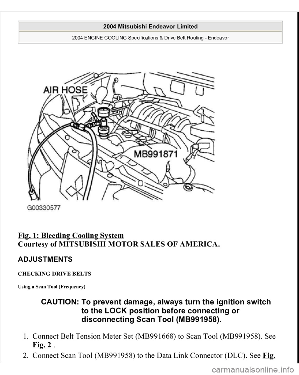
Fig. 1: Bleeding Cooling System
Courtesy of MITSUBISHI MOTOR SALES OF AMERICA.
ADJUSTMENTS CHECKING DRIVE BELTS Using a Scan Tool (Frequency) 1. Connect Belt Tension Meter Set (MB991668) to Scan Tool (MB991958). See
Fig. 2
.
2. Connect Scan Tool
(MB991958
) to the Data Link Connector
(DLC
). See Fi
g.
CAUTION: To prevent damage, always turn the ignition switch
to the LOCK position before connecting or
disconnecting Scan Tool (MB991958).
2004 Mitsubishi Endeavor Limited
2004 ENGINE COOLING Specifications & Drive Belt Routing - Endeavor
Page 1068 of 3870
2 .
3. Turn the ignition switch to the ON position and select BELT TENSION
MEASUREMENT from the menu screen on Scan Tool (MB991958).
4. Hold Microphone (part of Belt Drive Meter Set) (MB991668) near the center
of the drive belt between the pulleys away from the rear surface of the belt and
perpendicular to the belt (no more then 15 degrees in either direction). See Fi
g.
3 and Fig. 4
.
5. Gently tap the middle of the belt between the pulleys with your finger, and
check that the vibration frequency of the belt is within specification. See Fig. 3
and Fig. 4
. See DRIVE BELT ADJUSTMENT SPECIFICATIONS
table.
CAUTION: Temperature of the surface of the belt should be
as close possible to underhood temperature.
CAUTION: DO NOT let contaminants such as water or oil get
onto the microphone. If strong gusts of wind
blow against the microphone or if there are any
loud sources of noise nearby, the values
measured by the microphone may not
correspond to actual values. DO NOT take
measurement while engine is running.
2004 Mitsubishi Endeavor Limited
2004 ENGINE COOLING Specifications & Drive Belt Routing - Endeavor
Page 1069 of 3870
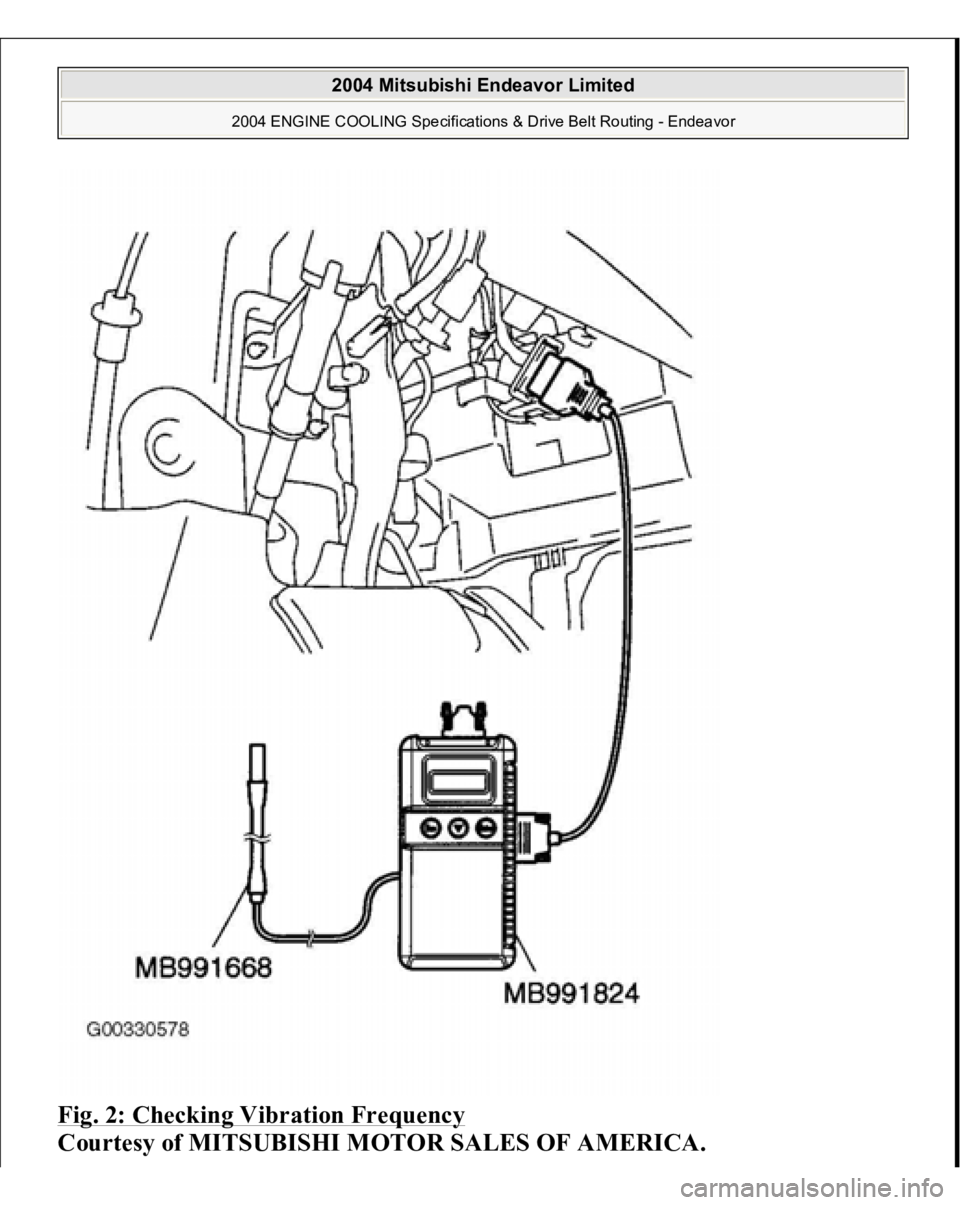
Fig. 2: Checking Vibration Frequency
Courtesy of MITSUBISHI MOTOR SALES OF AMERICA.
2004 Mitsubishi Endeavor Limited
2004 ENGINE COOLING Specifications & Drive Belt Routing - Endeavor