Page 1078 of 3870
2. Adjust the belt vibration frequency, tension, or deflection amount using the
adjusting bolt according to specifications. See Fig. 10
. See DRIVE BELT
ADJUSTMENT SPECIFICATIONS
table.
3. Tighten the lock nut to 29-43 ft. lbs. See Fig. 10
.
4. Tighten the adjusting bolt to 35-53 INCH lbs. (4-6 N.m). See Fig. 10
.
5. Check the belt vibration frequency, tension, or deflection and readjust as
necessary. See DRIVE BELT ADJUSTMENT SPECIFICATIONS table.
Fig. 10: Adjusting Power Steering Pump Drive Belt
Courtesy of MITSUBISHI MOTOR SALES OF AMERICA.
DRIVE BELT ROUTIN
G
CAUTION: Check after turning the crankshaft one or more
rotations clockwise.
2004 Mitsubishi Endeavor Limited
2004 ENGINE COOLING Specifications & Drive Belt Routing - Endeavor
Page 1079 of 3870
Fig. 11: Drive Belt Routing (Generator Belt)
Courtesy of MITSUBISHI MOTOR SALES OF AMERICA.
2004 Mitsubishi Endeavor Limited
2004 ENGINE COOLING Specifications & Drive Belt Routing - Endeavor
Page 1080 of 3870
Fig. 12: Drive Belt Routing Power Steering Pump Belt)
Courtesy of MITSUBISHI MOTOR SALES OF AMERICA.
SPECIFICATIONS COOLING SYSTEM SPECIFICATIONS COOLING SYSTEM SPECIFICATIONS Application
Specification
Coolant Replacement Interval
60,000 Miles
Coolant CapacityAWDWith Towing Kit
10.1 Qts. (9.6L)
Without Towing Kit
9.5 Qts. (9.0L)
FWD
9.5 Qts. (9.0L)
Pressure Cap
14-18 psi (.98-1.27
2004 Mitsubishi Endeavor Limited
2004 ENGINE COOLING Specifications & Drive Belt Routing - Endeavor
Page 1081 of 3870
kg/cm
2 )
ThermostatStarts To Open
187-193°F (86.5-89.5°
C)
Fully Opens
212°F (100°C)
2004 Mitsubishi Endeavor Limited
2004 ENGINE COOLING Specifications & Drive Belt Routing - Endeavor
Page 1098 of 3870

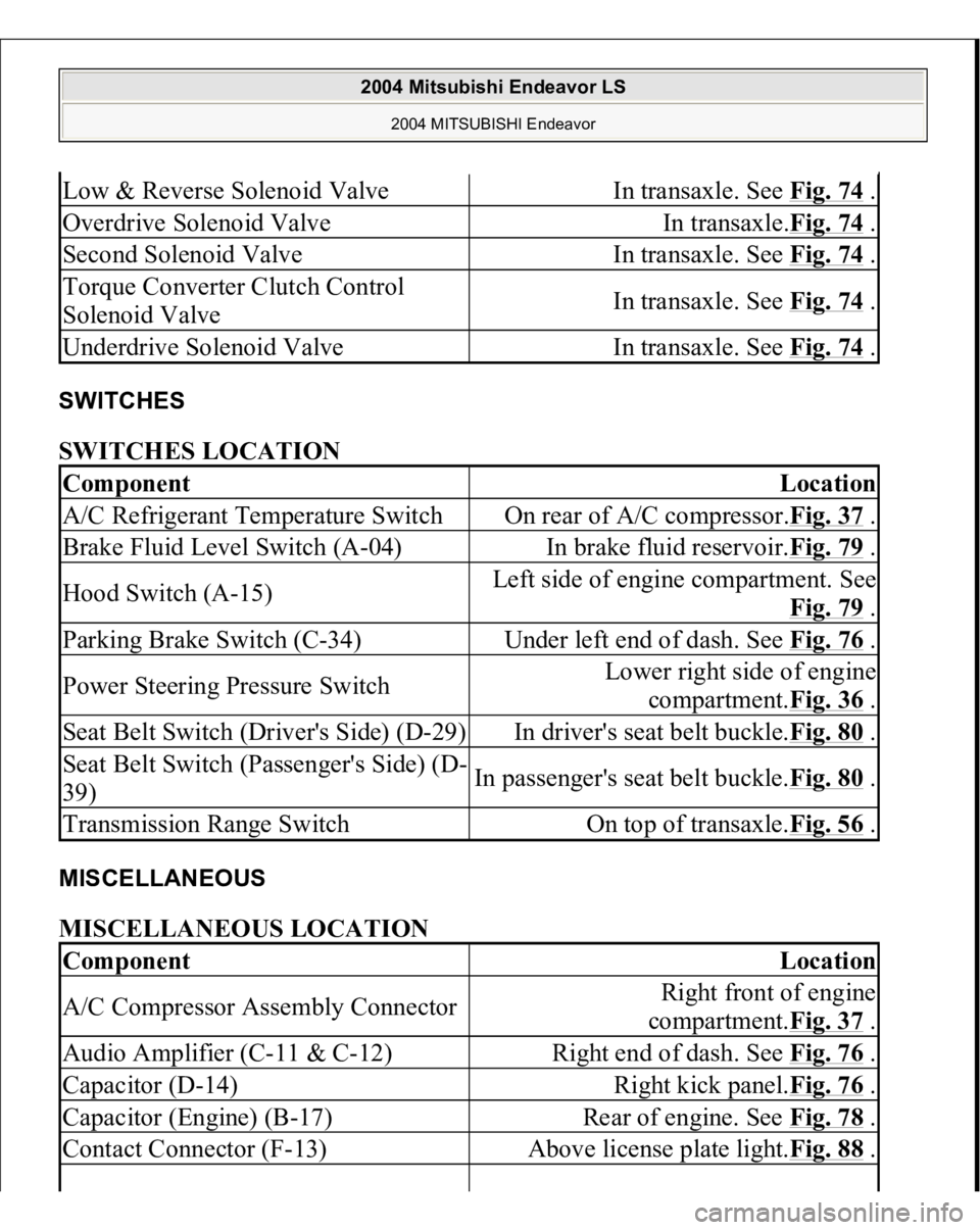
SWITCHES SWITCHES LOCATION MISCELLANEOUS MISCELLANEOUS LOCATION Low & Reverse Solenoid Valve
In transaxle. See Fig. 74
.
Overdrive Solenoid Valve
In transaxle.Fig. 74
.
Second Solenoid Valve
In transaxle. See Fig. 74
.
Torque Converter Clutch Control
Solenoid Valve
In transaxle. See Fig. 74
.
Underdrive Solenoid Valve
In transaxle. See Fig. 74
.
Component
Location
A/C Refrigerant Temperature Switch
On rear of A/C compressor.Fig. 37
.
Brake Fluid Level Switch (A-04)
In brake fluid reservoir.Fig. 79
.
Hood Switch (A-15)
Left side of engine compartment. See
Fig. 79
.
Parking Brake Switch (C-34)
Under left end of dash. See Fig. 76
.
Power Steering Pressure Switch
Lower right side of engine
compartment.Fig. 36
.
Seat Belt Switch (Driver's Side) (D-29)
In driver's seat belt buckle.Fig. 80
.
Seat Belt Switch (Passenger's Side) (D-
39)
In passenger's seat belt buckle.Fig. 80
.
Transmission Range Switch
On top of transaxle.Fig. 56
.
Component
Location
A/C Compressor Assembly Connector
Right front of engine
compartment.Fig. 37
.
Audio Amplifier (C-11 & C-12)
Right end of dash. See Fig. 76
.
Capacitor (D-14)
Right kick panel.Fig. 76
.
Capacitor (Engine) (B-17)
Rear of engine. See Fig. 78
.
Contact Connector (F-13)
Above license plate light.Fig. 88
.
2004 Mitsubishi Endeavor LS
2004 MITSUBISHI Endeavor
Page 1099 of 3870

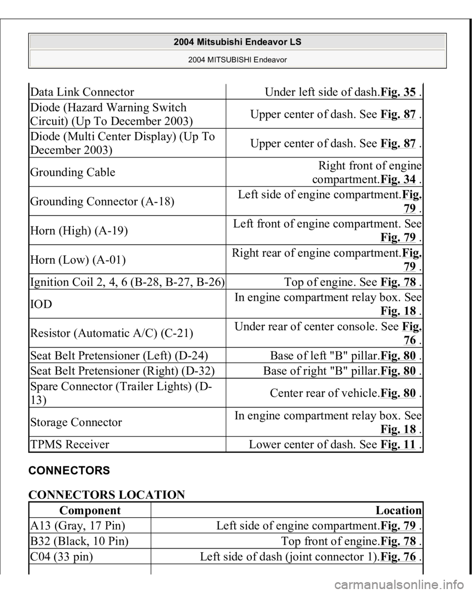
CONNECTORS CONNECTORS LOCATION Data Link Connector
Under left side of dash.Fig. 35
.
Diode (Hazard Warning Switch
Circuit) (Up To December 2003)
Upper center of dash. See Fig. 87
.
Diode (Multi Center Display) (Up To
December 2003)
Upper center of dash. See Fig. 87
.
Grounding Cable
Right front of engine
compartment.Fig. 34
.
Grounding Connector (A-18)
Left side of engine compartment.Fig.
79 .
Horn (High) (A-19)
Left front of engine compartment. See
Fig. 79
.
Horn (Low) (A-01)
Right rear of engine compartment.Fi
g.
79 .
Ignition Coil 2, 4, 6 (B-28, B-27, B-26)
Top of engine. See Fig. 78
.
IOD
In engine compartment relay box. See
Fig. 18
.
Resistor (Automatic A/C) (C-21)
Under rear of center console. See Fi
g.
76 .
Seat Belt Pretensioner (Left) (D-24)
Base of left "B" pillar.Fig. 80
.
Seat Belt Pretensioner (Right) (D-32)
Base of right "B" pillar.Fig. 80
.
Spare Connector (Trailer Lights) (D-
13)
Center rear of vehicle.Fig. 80
.
Storage Connector
In engine compartment relay box. See
Fig. 18
.
TPMS Receiver
Lower center of dash. See Fig. 11
.
Component
Location
A13 (Gray, 17 Pin)
Left side of engine compartment.Fig. 79
.
B32 (Black, 10 Pin)
Top front of engine.Fig. 78
.
C04 (33 pin)
Left side of dash (joint connector 1).Fig. 76
.
2004 Mitsubishi Endeavor LS
2004 MITSUBISHI Endeavor
Page 1188 of 3870
2004 ENGINE
Engine Cooling - Endeavor
GENERAL DESCRIPTION The cooling system is designed to keep every part of the engine at appropriate
temperature in whatever condition the engine may be operated. The cooling method
is of the water-cooled, pressure forced circulation type in which the water pump
pressurizes coolant and circulates it throughout the engine. If the coolant
temperature exceeds the prescribed temperature, the thermostat opens to circulate
the coolant through the radiator as well so that the heat absorbed by the coolant may
be radiated into the air. The water pump is of the centrifugal type and is driven by
the drive belt from the crankshaft. The radiator is the corrugated fin, down flow
type. CONSTRUCTION DIAGRAM Fig. 1: Identifying Engine Cooling Construction Diagram
2004 Mitsubishi Endeavor Limited 2004 ENGINE Engine Cooling - Endeavor
2004 Mitsubishi Endeavor Limited 2004 ENGINE Engine Cooling - Endeavor
Page 1189 of 3870
Courtesy of MITSUBISHI MOTOR SALES OF AMERICA
.
SPECIAL TOOLS Fig. 2: Identifying Engine Cooling Special Tools
Courtesy of MITSUBISHI MOTOR SALES OF AMERICA.
ENGINE COOLING DIAGNOSIS INTRODUCTION The system cools the engine so that it does not over-heat and maintains the engine
at an optimum temperature. The system components are the radiator, water pump,
thermostat, condenser fan assembly. Possible faults include low coolant,
contamination, belt loosening and component damage. TROUBLESHOOTING STRATEG
Y
2004 Mitsubishi Endeavor Limited 2004 ENGINE Engine Cooling - Endeavor