Page 2314 of 3870
Fig. 228: Locating Connector C
-201
Courtesy of MITSUBISHI MOTOR SALES OF AMERICA.
3. Measure the voltage between terminal 1 and ground.
The measured value should be approximately 12 volts (battery
positive voltage).
Q: Is the measured voltage approximately 12 volts?
YES:
Go to Step 10 .
NO:
Go to Ste
p 9.
2004 Mitsubishi Endeavor LS
2004 HVAC Heater Air Conditioning, Ventilation - Endeavor
Page 2336 of 3870
Fig. 246: Locating Connector C
-17
Courtesy of MITSUBISHI MOTOR SALES OF AMERICA.
3. Measure the voltage between terminal 28 and ground.
The measured value should be approximately 12 volts (battery positive volta
ge).
2004 Mitsubishi Endeavor LS
2004 HVAC Heater Air Conditioning, Ventilation - Endeavor
Page 2341 of 3870
Fig. 250: Locating Connectors C
-211 And C
-215
Courtesy of MITSUBISHI MOTOR SALES OF AMERICA.
STEP 4. Measure the voltage at A/C-ECU connector C-17.
1. Disconnect A/C-ECU connector C-17 and measure the voltage at the
harness side.
2. Turn the ignition switch to the "ACC" position.
Fig. 251: Locating Connector C
-17
Courtesy of MITSUBISHI MOTOR SALES OF AMERICA.
3. Measure the voltage between terminal 36 and ground.
The measured value should be approximately 12 volts (battery
positive voltage).
2004 Mitsubishi Endeavor LS
2004 HVAC Heater Air Conditioning, Ventilation - Endeavor
Page 2346 of 3870
STEP 6. Measure the voltage at A/C-ECU connector C-16.
1. Disconnect A/C-ECU connector C-16 and measure the voltage at the
harness side.
Fig. 255: Locating Connector C
-16
Courtesy of MITSUBISHI MOTOR SALES OF AMERICA.
2. Measure the voltage between terminal 3 and ground.
The measured value should be approximately 12 volts (battery positive volta
ge).
2004 Mitsubishi Endeavor LS
2004 HVAC Heater Air Conditioning, Ventilation - Endeavor
Page 2374 of 3870
A/C COMPRESSOR CLUTCH RELAY CONTINUITY CHECK BATTERY VOLTAGE
TESTER
CONNECTION
SPECIFIED
CONDITION
Not applied
4 - 5
Open circuit
Connect terminal 1 to the
positive battery terminal
Connect terminal 3 to the
negative battery terminal
4 - 5
Less than 2 ohms
2004 Mitsubishi Endeavor LS
2004 HVAC Heater Air Conditioning, Ventilation - Endeavor
Page 2376 of 3870
Fig. 278: Identifying A/C Compressor Clutch Relay
Courtesy of MITSUBISHI MOTOR SALES OF AMERICA.
A/C COMPRESSOR CLUTCH RELAY CONTINUITY CHART
FAN CONTROL RELAY CONTINUITY CHECK BATTERY VOLTAGE
TESTER
CONNECTION
SPECIFIED
CONDITION
Not applied
1 - 4
Open circuit
Connect terminal 2 to the
positive battery terminal
Connect terminal 3 to the
negative battery terminal
1 - 4
Less than 2 ohms
2004 Mitsubishi Endeavor LS
2004 HVAC Heater Air Conditioning, Ventilation - Endeavor
Page 2378 of 3870

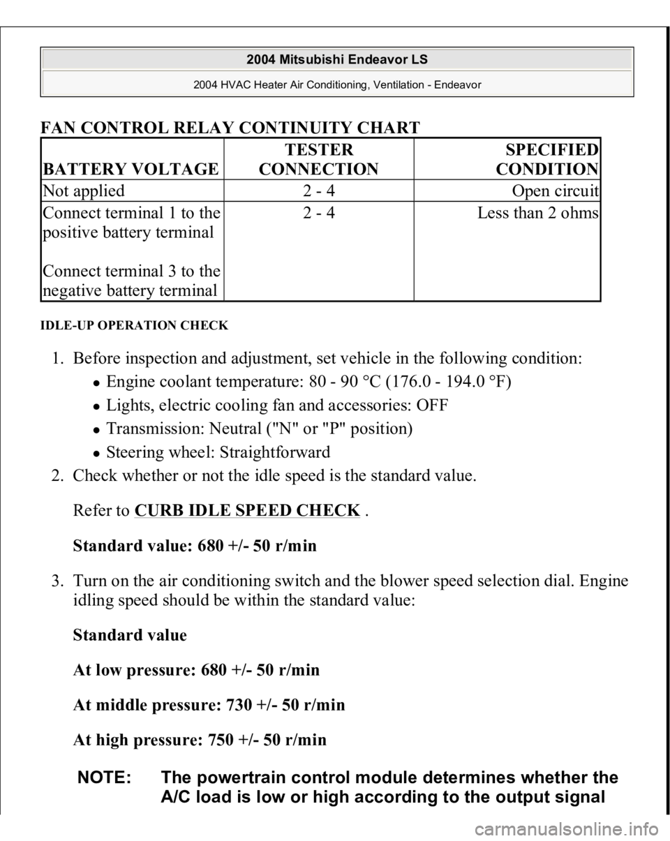
FAN CONTROL RELAY CONTINUITY CHART
IDLE-UP OPERATION CHECK 1. Before inspection and adjustment, set vehicle in the following condition:
Engine coolant temperature: 80 - 90 °C (176.0 - 194.0 °F) Lights, electric cooling fan and accessories: OFF Transmission: Neutral ("N" or "P" position) Steering wheel: Straightforward
2. Check whether or not the idle speed is the standard value.
Refer to
CURB IDLE SPEED CHECK
.
Standard value: 680 +/- 50 r/min
3. Turn on the air conditioning switch and the blower speed selection dial. Engine
idling speed should be within the standard value:
Standard value
At low pressure: 680 +/- 50 r/min
At middle pressure: 730 +/- 50 r/min
At high pressure: 750 +/- 50 r/min
BATTERY VOLTAGE
TESTER
CONNECTION
SPECIFIED
CONDITION
Not applied
2 - 4
Open circuit
Connect terminal 1 to the
positive battery terminal
Connect terminal 3 to the
negative battery terminal
2 - 4
Less than 2 ohms
NOTE: The powertrain control module determines whether the
A/C load is low or high according to the output signal
2004 Mitsubishi Endeavor LS
2004 HVAC Heater Air Conditioning, Ventilation - Endeavor
Page 2389 of 3870
INSPECTION AIR MIXING DAMPER CONTROL MOTOR CHECK Check the air mix damper control motor by the following procedures. Fig. 289: Identifying Damper Control Motor Hot And Cool Position
Courtesy of MITSUBISHI MOTOR SALES OF AMERICA.
AIR MIX DAMPER CONTROL MOTOR
CAUTION: Do not apply battery voltage when the damper is in
the MAX COOL or MAX HOT position.
LEVER POSITION
BATTERY
CONNECTION
LEVER OPERATION
At the MAX COOL
position
Connect terminal 1 to the
positive battery terminal
The lever moves from the
MAX COOL position to
2004 Mitsubishi Endeavor LS
2004 HVAC Heater Air Conditioning, Ventilation - Endeavor