Page 1047 of 3870

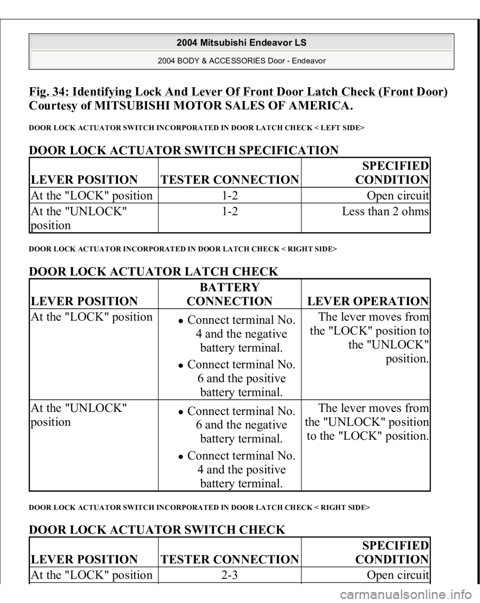
Fig. 34: Identifying Lock And Lever Of Front Door Latch Check (Front Door)
Courtesy of MITSUBISHI MOTOR SALES OF AMERICA.
DOOR LOCK ACTUATOR SWITCH INCORPORATED IN DOOR LATCH CHECK < LEFT SIDE> DOOR LOCK ACTUATOR SWITCH SPECIFICATION DOOR LOCK ACTUATOR INCORPORATED IN DOOR LATCH CHECK < RIGHT SIDE> DOOR LOCK ACTUATOR LATCH CHECK DOOR LOCK ACTUATOR SWITCH INCORPORATED IN DOOR LATCH CHECK < RIGHT SIDE> DOOR LOCK ACTUATOR SWITCH CHECK LEVER POSITION
TESTER CONNECTION
SPECIFIED
CONDITION
At the "LOCK" position
1-2
Open circuit
At the "UNLOCK"
position
1-2
Less than 2 ohms
LEVER POSITION
BATTERY
CONNECTION
LEVER OPERATION
At the "LOCK" position
Connect terminal No.
4 and the negative
battery terminal. Connect terminal No.
6 and the positive
battery terminal.
The lever moves from
the "LOCK" position to
the "UNLOCK"
position.
At the "UNLOCK"
position
Connect terminal No.
6 and the negative
battery terminal. Connect terminal No.
4 and the positive
battery terminal.
The lever moves from
the "UNLOCK" position
to the "LOCK" position.
LEVER POSITION
TESTER CONNECTION
SPECIFIED
CONDITION
At the "LOCK" position
2-3
Open circuit
2004 Mitsubishi Endeavor LS
2004 BODY & ACCESSORIES Door - Endeavor
Page 1048 of 3870
REAR DOOR LOCK ACTUATOR CHECK The illustration shows when the door lock actuator is viewed from outside the door. DOOR LOCK ACTUATOR INCORPORATED IN DOOR LATCH CHECK < LEFT SIDE> DOOR LOCK ACTUATOR LATCH CHECK At the "UNLOCK"
position
2-3
Less than 2 ohms
LEVER POSITION
BATTERY
CONNECTION
LEVER OPERATION
At the "LOCK" position
Connect terminal No.
4 and the negative
battery terminal. Connect terminal No.
6 and the positive
battery terminal.
The lever moves from
the "LOCK" position to
the "UNLOCK"
position.
At the "UNLOCK"
position
Connect terminal No.
6 and the negative
battery terminal. Connect terminal No.
4 and the positive
battery terminal.
The lever moves from
the "UNLOCK" position
to the "LOCK" position.
2004 Mitsubishi Endeavor LS
2004 BODY & ACCESSORIES Door - Endeavor
Page 1050 of 3870

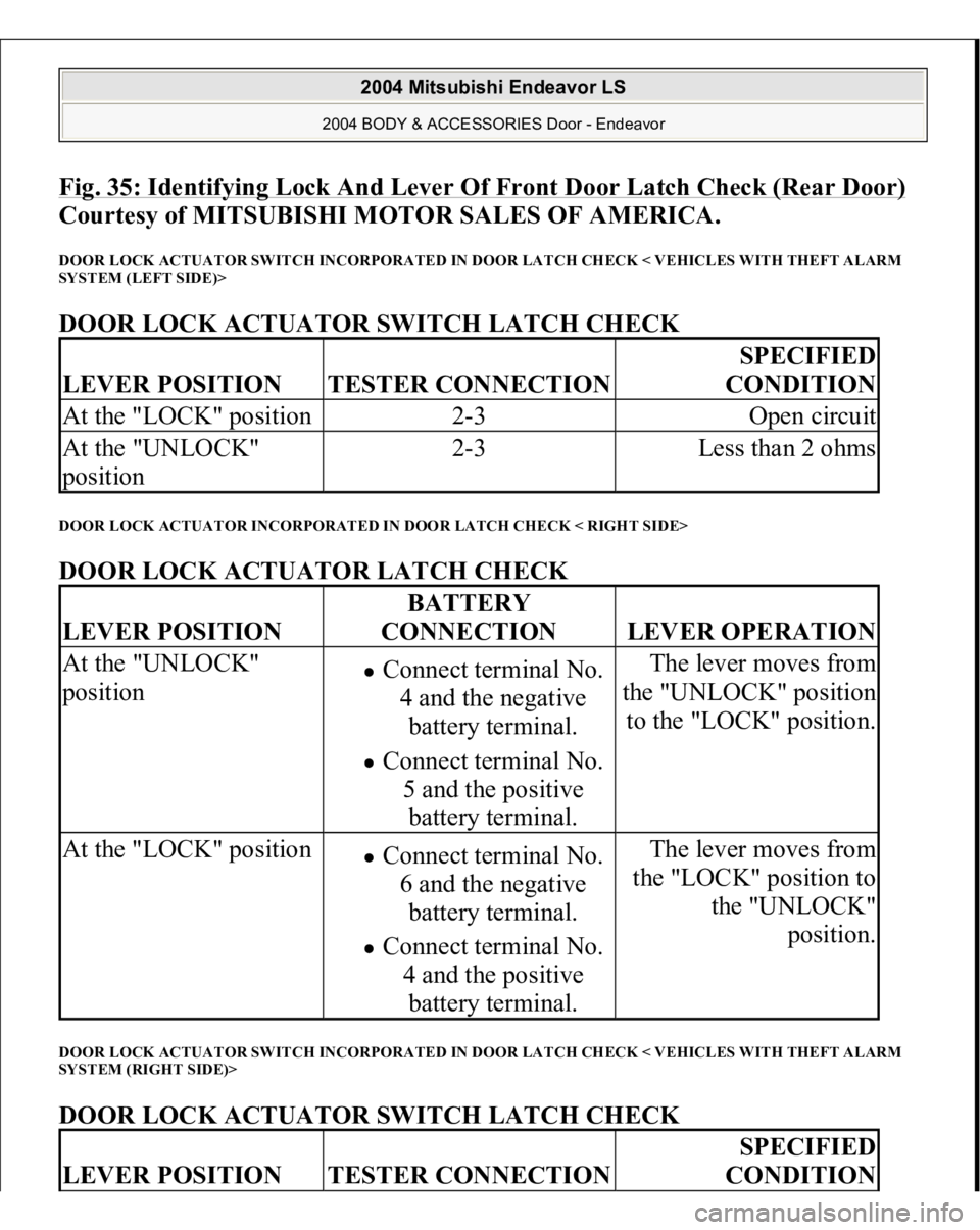
Fig. 35: Identifying Lock And Lever Of Front Door Latch Check (Rear Door)
Courtesy of MITSUBISHI MOTOR SALES OF AMERICA.
DOOR LOCK ACTUATOR SWITCH INCORPORATED IN DOOR LATCH CHECK < VEHICLES WITH THEFT ALARM
SYSTEM (LEFT SIDE)> DOOR LOCK ACTUATOR SWITCH LATCH CHECK DOOR LOCK ACTUATOR INCORPORATED IN DOOR LATCH CHECK < RIGHT SIDE> DOOR LOCK ACTUATOR LATCH CHECK DOOR LOCK ACTUATOR SWITCH INCORPORATED IN DOOR LATCH CHECK < VEHICLES WITH THEFT ALARM
SYSTEM (RIGHT SIDE)> DOOR LOCK ACTUATOR SWITCH LATCH CHECK LEVER POSITION
TESTER CONNECTION
SPECIFIED
CONDITION
At the "LOCK" position
2-3
Open circuit
At the "UNLOCK"
position
2-3
Less than 2 ohms
LEVER POSITION
BATTERY
CONNECTION
LEVER OPERATION
At the "UNLOCK"
position
Connect terminal No.
4 and the negative
battery terminal. Connect terminal No.
5 and the positive
battery terminal.
The lever moves from
the "UNLOCK" position
to the "LOCK" position.
At the "LOCK" position
Connect terminal No.
6 and the negative
battery terminal. Connect terminal No.
4 and the positive
battery terminal.
The lever moves from
the "LOCK" position to
the "UNLOCK"
position.
LEVER POSITION
TESTER CONNECTION
SPECIFIED
CONDITION
2004 Mitsubishi Endeavor LS
2004 BODY & ACCESSORIES Door - Endeavor
Page 1094 of 3870

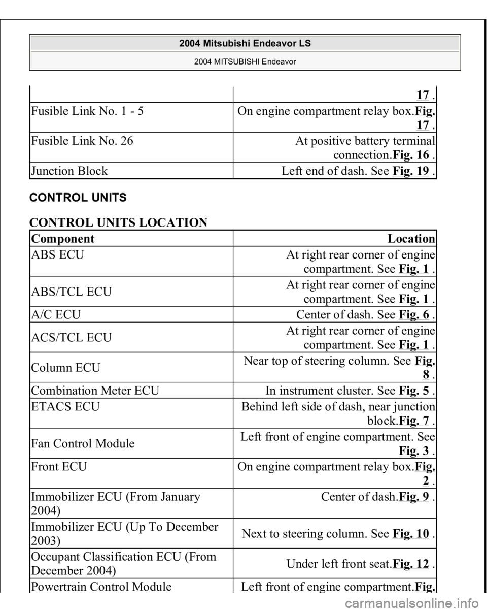
CONTROL UNITS CONTROL UNITS LOCATION
17 .
Fusible Link No. 1 - 5
On engine compartment relay box.Fi
g.
17 .
Fusible Link No. 26
At positive battery terminal
connection.Fig. 16
.
Junction Block
Left end of dash. See Fig. 19
.
Component
Location
ABS ECU
At right rear corner of engine
compartment. See Fig. 1
.
ABS/TCL ECU
At right rear corner of engine
compartment. See Fig. 1
.
A/C ECU
Center of dash. See Fig. 6
.
ACS/TCL ECU
At right rear corner of engine
compartment. See Fig. 1
.
Column ECU
Near top of steering column. See Fi
g. 8 .
Combination Meter ECU
In instrument cluster. See Fig. 5
.
ETACS ECU
Behind left side of dash, near junction
block.Fig. 7
.
Fan Control Module
Left front of engine compartment. See
Fig. 3
.
Front ECU
On engine compartment relay box.Fi
g. 2 .
Immobilizer ECU (From January
2004)
Center of dash.Fig. 9
.
Immobilizer ECU (Up To December
2003)
Next to steering column. See Fig. 10
.
Occupant Classification ECU (From
December 2004)
Under left front seat.Fig. 12
.
Powertrain Control Modul
e
Left front of en
gine com
partment.Fi
g.
2004 Mitsubishi Endeavor LS
2004 MITSUBISHI Endeavor
Page 1200 of 3870
Fig. 8: Disconnecting Fan Control Module Connector
Courtesy of MITSUBISHI MOTOR SALES OF AMERICA.
2. Measure the voltage between terminal number 3 and ground.
When the ignition switch is turned to the "ON" position, voltage
should measure battery positive voltage.
2004 Mitsubishi Endeavor Limited 2004 ENGINE Engine Cooling - Endeavor
Page 1201 of 3870
Fig. 9: Measuring Voltage Between Terminal 3 & Ground
Courtesy of MITSUBISHI MOTOR SALES OF AMERICA.
Q: Is there voltage battery positive voltage when the ignition switch is
turned to the "ON" position?
YES: Go to Step 8 .
NO: Go to Step 2.
STEP 2. Check the fan control relay.
Refer to FAN CONTROL RELAY CONTINUITY CHECK
.
Q: Is the fan control relay in good condition?
YES: Go to Step 3.
2004 Mitsubishi Endeavor Limited 2004 ENGINE Engine Cooling - Endeavor
Page 1245 of 3870
11. After repeatedly revving the engine up to 3,000 r/min several times, stop the
engine.
12. Remove the radiator cap after the engine has cooled, and pour in coolant up to
the brim. Reinstall the cap.
13. Add coolant to the radiator condenser tank assembly between the "FULL" and
"LOW" mark if necessary. ENGINE COOLANT CONCENTRATION TEST Refer to RECOMMENDED LUBRICANTS AND LUBRICANT CAPACITIES
.
FAN CONTROL MODULE CHECK 1. Remove the fan control module connector.
2. Turn the ignition switch to the "ON" position, and measure the voltage
between the harness-side connector terminals.
Standard value: Battery positive voltage
CAUTION: Do not overfill the radiator condenser tank
assembly.
2004 Mitsubishi Endeavor Limited 2004 ENGINE Engine Cooling - Endeavor
Page 1247 of 3870
Fig. 44: Measuring Voltage Between Fan Control Module
-Side Connector
Terminals
Courtesy of MITSUBISHI MOTOR SALES OF AMERICA.
6. Turn the A/C switch to the "ON" position.
7. Measure the voltage between the fan control module-side connector terminals
while the fan is running. The voltage should repeat the values 1) and 2) below.
Standard value:
1.8.2+/-2.6 V
2.Battery positive voltage+/-2.6 V
8. If the voltage does not repeatedly change as indicated, replace the radiator fan
motor.
FAN CONTROL RELAY CONTINUITY CHECK
2004 Mitsubishi Endeavor Limited 2004 ENGINE Engine Cooling - Endeavor