Page 1077 of 3870
1. Loosen the tensioner pulley fixing bolt. See Fig. 9
.
2. Temporarily tighten the tensioner pulley fixing nut to 7-15 ft. lbs. (10-20 N.m).
Ensure belt frequency, tension, or deflection is to specification. See DRIVE
BELT ADJUSTMENT SPECIFICATIONS
table.
Fig. 9: Adjusting Generator Drive Belt
Courtesy of MITSUBISHI MOTOR SALES OF AMERICA.
Power Steering Pump Belt 1. Loosen the tensioner pulley lock nut. See Fig. 10
.
NOTE: The tension will increase when the turning the adjusting
bolt clockwise, and decrease when turning adjusting
bolt counterclockwise.
2004 Mitsubishi Endeavor Limited
2004 ENGINE COOLING Specifications & Drive Belt Routing - Endeavor
Page 1078 of 3870
2. Adjust the belt vibration frequency, tension, or deflection amount using the
adjusting bolt according to specifications. See Fig. 10
. See DRIVE BELT
ADJUSTMENT SPECIFICATIONS
table.
3. Tighten the lock nut to 29-43 ft. lbs. See Fig. 10
.
4. Tighten the adjusting bolt to 35-53 INCH lbs. (4-6 N.m). See Fig. 10
.
5. Check the belt vibration frequency, tension, or deflection and readjust as
necessary. See DRIVE BELT ADJUSTMENT SPECIFICATIONS table.
Fig. 10: Adjusting Power Steering Pump Drive Belt
Courtesy of MITSUBISHI MOTOR SALES OF AMERICA.
DRIVE BELT ROUTIN
G
CAUTION: Check after turning the crankshaft one or more
rotations clockwise.
2004 Mitsubishi Endeavor Limited
2004 ENGINE COOLING Specifications & Drive Belt Routing - Endeavor
Page 1079 of 3870
Fig. 11: Drive Belt Routing (Generator Belt)
Courtesy of MITSUBISHI MOTOR SALES OF AMERICA.
2004 Mitsubishi Endeavor Limited
2004 ENGINE COOLING Specifications & Drive Belt Routing - Endeavor
Page 1080 of 3870
Fig. 12: Drive Belt Routing Power Steering Pump Belt)
Courtesy of MITSUBISHI MOTOR SALES OF AMERICA.
SPECIFICATIONS COOLING SYSTEM SPECIFICATIONS COOLING SYSTEM SPECIFICATIONS Application
Specification
Coolant Replacement Interval
60,000 Miles
Coolant CapacityAWDWith Towing Kit
10.1 Qts. (9.6L)
Without Towing Kit
9.5 Qts. (9.0L)
FWD
9.5 Qts. (9.0L)
Pressure Cap
14-18 psi (.98-1.27
2004 Mitsubishi Endeavor Limited
2004 ENGINE COOLING Specifications & Drive Belt Routing - Endeavor
Page 1081 of 3870
kg/cm
2 )
ThermostatStarts To Open
187-193°F (86.5-89.5°
C)
Fully Opens
212°F (100°C)
2004 Mitsubishi Endeavor Limited
2004 ENGINE COOLING Specifications & Drive Belt Routing - Endeavor
Page 1093 of 3870

2004 MITSUBISH
I
Endeavor
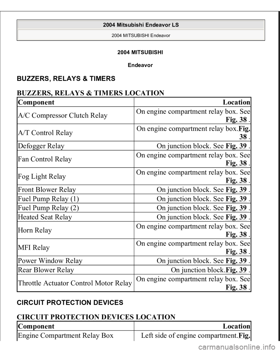
BUZZERS, RELAYS & TIMERS BUZZERS, RELAYS & TIMERS LOCATION CIRCUIT PROTECTION DEVICES CIRCUIT PROTECTION DEVICES LOCATION Component
Location
A/C Compressor Clutch Relay
On engine compartment relay box. See
Fig. 38
.
A/T Control Relay
On engine compartment relay box.Fig.
38 .
Defogger Relay
On junction block. See Fig. 39
.
Fan Control Relay
On engine compartment relay box. See
Fig. 38
.
Fog Light Relay
On engine compartment relay box. See
Fig. 38
.
Front Blower Relay
On junction block. See Fig. 39
.
Fuel Pump Relay (1)
On junction block. See Fig. 39
.
Fuel Pump Relay (2)
On junction block. See Fig. 39
.
Heated Seat Relay
On junction block. See Fig. 39
.
Horn Relay
On engine compartment relay box. See
Fig. 38
.
MFI Relay
On engine compartment relay box. See
Fig. 38
.
Power Window Relay
On junction block. See Fig. 39
.
Rear Blower Relay
On junction block.Fig. 39
.
Throttle Actuator Control Motor Relay
On engine compartment relay box. See
Fig. 38
.
Component
Location
Engine Compartment Relay Box
Left side of engine compartment.Fi
g.
2004 Mitsubishi Endeavor LS
2004 MITSUBISHI Endeavor
2004 Mitsubishi Endeavor LS
2004 MITSUBISHI Endeavor
Page 1094 of 3870

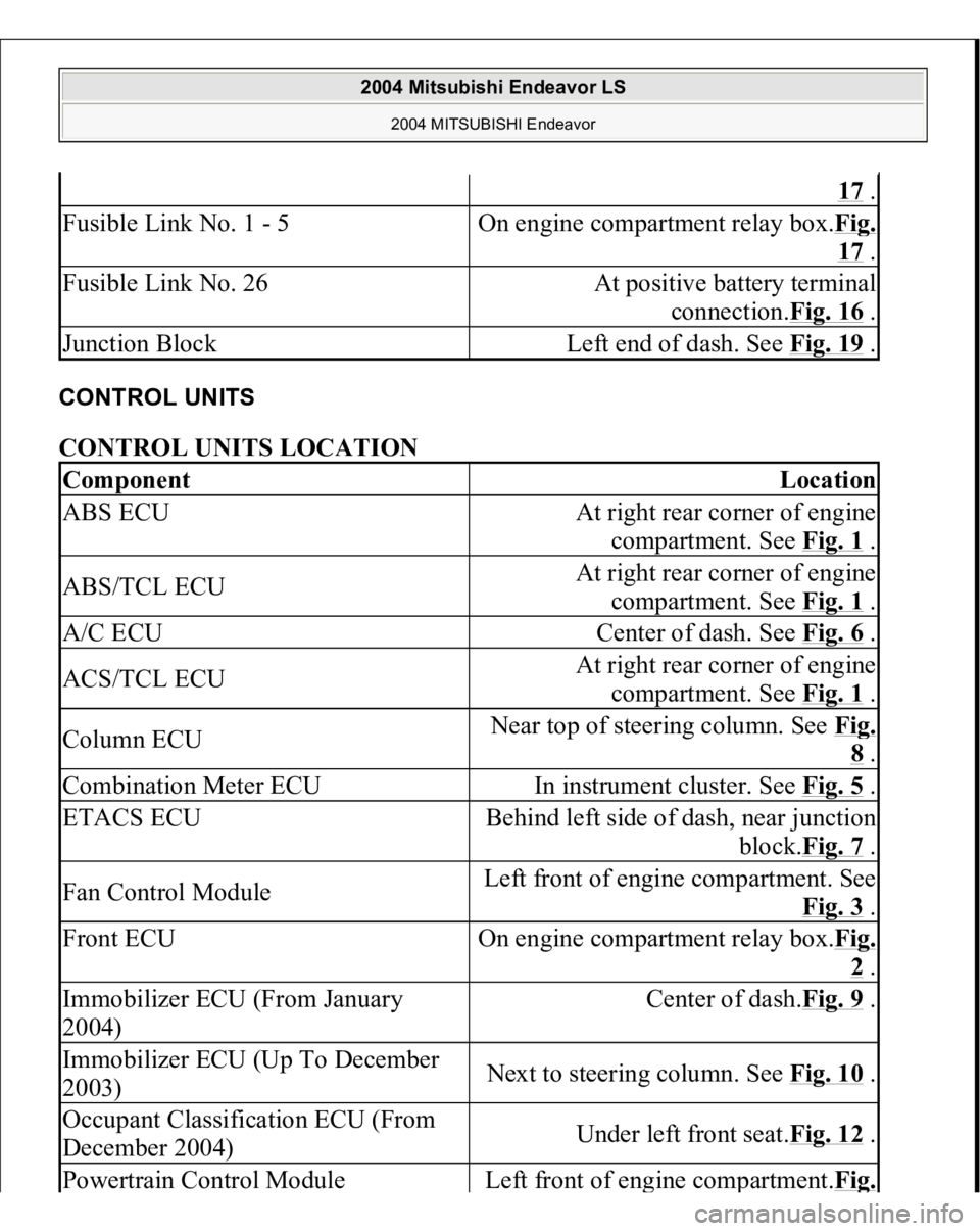
CONTROL UNITS CONTROL UNITS LOCATION
17 .
Fusible Link No. 1 - 5
On engine compartment relay box.Fi
g.
17 .
Fusible Link No. 26
At positive battery terminal
connection.Fig. 16
.
Junction Block
Left end of dash. See Fig. 19
.
Component
Location
ABS ECU
At right rear corner of engine
compartment. See Fig. 1
.
ABS/TCL ECU
At right rear corner of engine
compartment. See Fig. 1
.
A/C ECU
Center of dash. See Fig. 6
.
ACS/TCL ECU
At right rear corner of engine
compartment. See Fig. 1
.
Column ECU
Near top of steering column. See Fi
g. 8 .
Combination Meter ECU
In instrument cluster. See Fig. 5
.
ETACS ECU
Behind left side of dash, near junction
block.Fig. 7
.
Fan Control Module
Left front of engine compartment. See
Fig. 3
.
Front ECU
On engine compartment relay box.Fi
g. 2 .
Immobilizer ECU (From January
2004)
Center of dash.Fig. 9
.
Immobilizer ECU (Up To December
2003)
Next to steering column. See Fig. 10
.
Occupant Classification ECU (From
December 2004)
Under left front seat.Fig. 12
.
Powertrain Control Modul
e
Left front of en
gine com
partment.Fi
g.
2004 Mitsubishi Endeavor LS
2004 MITSUBISHI Endeavor
Page 1095 of 3870

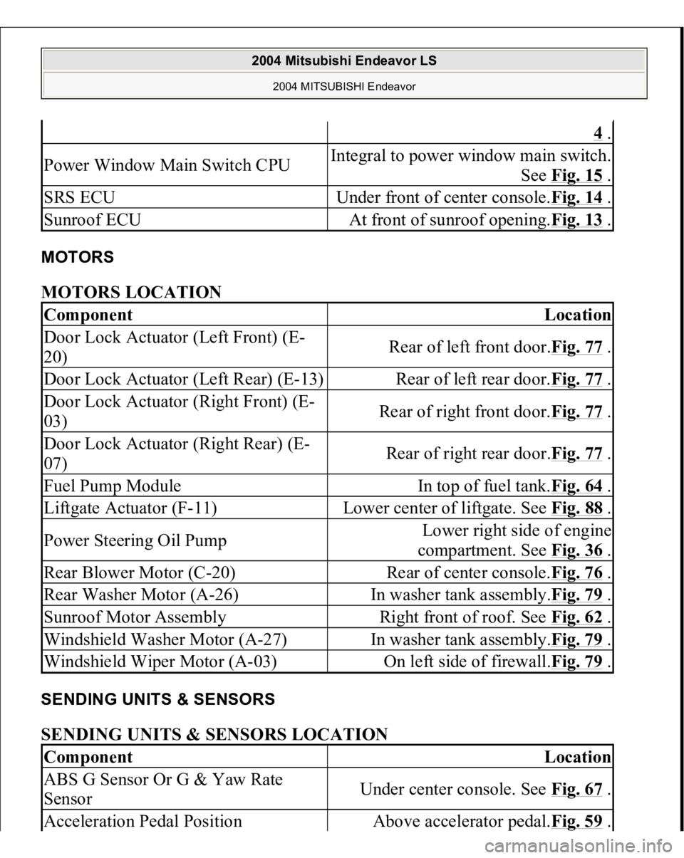
MOTORS MOTORS LOCATION SENDING UNITS & SENSORS SENDING UNITS & SENSORS LOCATION
4 .
Power Window Main Switch CPU
Integral to power window main switch.
See Fig. 15
.
SRS ECU
Under front of center console.Fig. 14
.
Sunroof ECU
At front of sunroof opening.Fig. 13
.
Component
Location
Door Lock Actuator (Left Front) (E-
20)
Rear of left front door.Fig. 77
.
Door Lock Actuator (Left Rear) (E-13)
Rear of left rear door.Fig. 77
.
Door Lock Actuator (Right Front) (E-
03)
Rear of right front door.Fig. 77
.
Door Lock Actuator (Right Rear) (E-
07)
Rear of right rear door.Fig. 77
.
Fuel Pump Module
In top of fuel tank.Fig. 64
.
Liftgate Actuator (F-11)
Lower center of liftgate. See Fig. 88
.
Power Steering Oil Pump
Lower right side of engine
compartment. See Fig. 36
.
Rear Blower Motor (C-20)
Rear of center console.Fig. 76
.
Rear Washer Motor (A-26)
In washer tank assembly.Fig. 79
.
Sunroof Motor Assembly
Right front of roof. See Fig. 62
.
Windshield Washer Motor (A-27)
In washer tank assembly.Fig. 79
.
Windshield Wiper Motor (A-03)
On left side of firewall.Fig. 79
.
Component
Location
ABS G Sensor Or G & Yaw Rate
Sensor
Under center console. See Fig. 67
.
Acceleration Pedal Position
Above accelerator pedal.Fig. 59
.
2004 Mitsubishi Endeavor LS
2004 MITSUBISHI Endeavor