Page 3528 of 3870
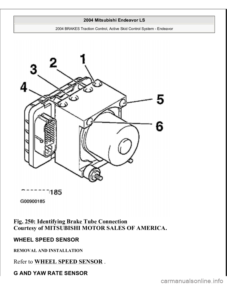
Fig. 250: Identifying Brake Tube Connection
Courtesy of MITSUBISHI MOTOR SALES OF AMERICA.
WHEEL SPEED SENSOR REMOVAL AND INSTALLATION Refer to WHEEL SPEED SENSOR
.
G AND YAW RATE SENSOR
2004 Mitsubishi Endeavor LS
2004 BRAKES Traction Control, Active Skid Control System - Endeavor
Page 3529 of 3870
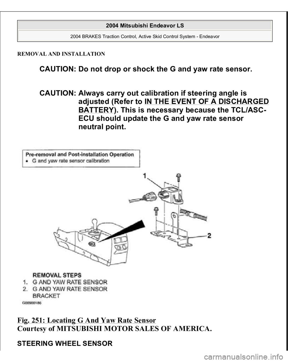
REMOVAL AND INSTALLATIONFig. 251: Locating G And Yaw Rate Sensor
Courtesy of MITSUBISHI MOTOR SALES OF AMERICA.
STEERING WHEEL SENSOR
CAUTION: Do not drop or shock the G and yaw rate sensor.
CAUTION: Always carry out calibration if steering angle is
adjusted (Refer to IN THE EVENT OF A DISCHARGED
BATTERY
). This is necessary because the TCL/ASC-
ECU should update the G and yaw rate sensor
neutral point.
2004 Mitsubishi Endeavor LS
2004 BRAKES Traction Control, Active Skid Control System - Endeavor
Page 3530 of 3870
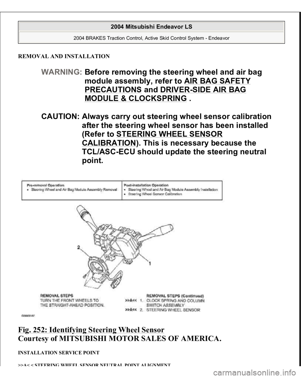
REMOVAL AND INSTALLATIONFig. 252: Identifying Steering Wheel Sensor
Courtesy of MITSUBISHI MOTOR SALES OF AMERICA.
INSTALLATION SERVICE POINT >>A< < STEERING WHEEL SENSOR NEUTRAL POINT ALIGNMEN
T
WARNING:Before removing the steering wheel and air bag
module assembly, refer to AIR BAG SAFETY
PRECAUTIONS
and DRIVER
-SIDE AIR BAG
MODULE & CLOCKSPRING
.
CAUTION: Always carry out steering wheel sensor calibration
after the steering wheel sensor has been installed
(Refer to STEERING WHEEL SENSOR
CALIBRATION
). This is necessary because the
TCL/ASC-ECU should update the steering neutral
point.
2004 Mitsubishi Endeavor LS
2004 BRAKES Traction Control, Active Skid Control System - Endeavor
Page 3547 of 3870
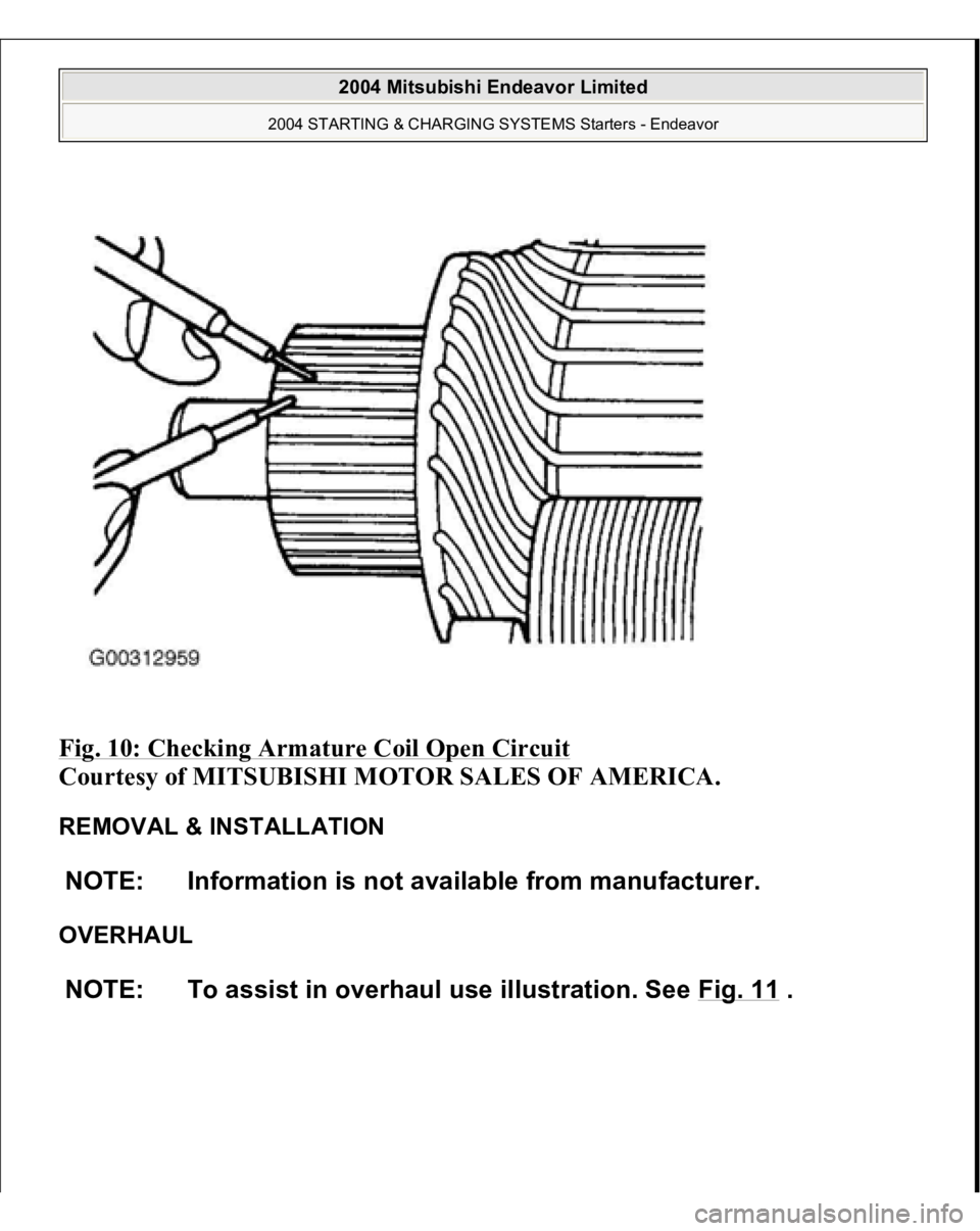
Fig. 10: Checking Armature Coil Open Circuit
Courtesy of MITSUBISHI MOTOR SALES OF AMERICA.
REMOVAL & INSTALLATION
OVERHAUL NOTE: Information is not available from manufacturer.
NOTE: To assist in overhaul use illustration. See Fig. 11
.
2004 Mitsubishi Endeavor Limited
2004 STARTING & CHARGING SYSTEMS Starters - Endeavor
Page 3563 of 3870
SUNROOF TIMER MECHANISM In cases except the following, the basic operation and jam preventing mechanism
will be maintained for thirty seconds after the ignition switch is turned to the LOCK
(OFF) position. (Sunroof timer function)
If you open a door within that period (i.e. a door switch is on), the sunroof
timer function will be cancelled immediately. If you turn the ignition switch to the LOCK (OFF) position while the timer is
working, the sunroof will continue moving until it close fully, regardless of the
time-out period.
SUNROOF ASSEMBLY REMOVAL AND INSTALLATION
4. Interrupt the sunroof
operation before the
sunroof is fully close.
interrupted.
2004 Mitsubishi Endeavor LS
2004 BODY & ACCESSORIES Sunroof Assembly - Endeavor
Page 3565 of 3870
Fig. 6: Removing/Installing Sunroof Assembly
Courtesy of MITSUBISHI MOTOR SALES OF AMERICA.
Required Special Tool:
MB991223: Harness set
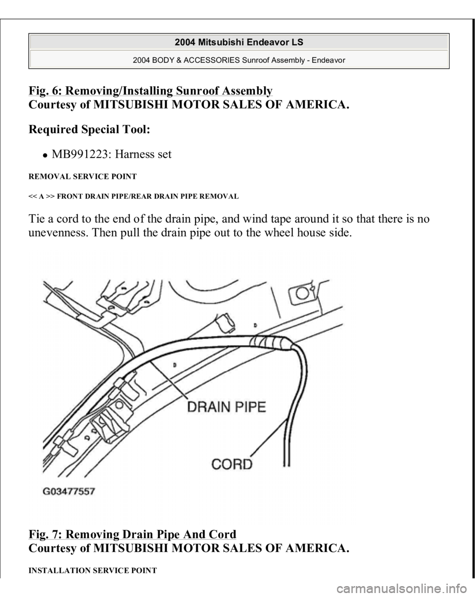
REMOVAL SERVICE POINT << A >> FRONT DRAIN PIPE/REAR DRAIN PIPE REMOVAL Tie a cord to the end of the drain pipe, and wind tape around it so that there is no
unevenness. Then pull the drain pipe out to the wheel house side.
Fig. 7: Removing Drain Pipe And Cord
Courtesy of MITSUBISHI MOTOR SALES OF AMERICA.
INSTALLATION SERVICE POINT
2004 Mitsubishi Endeavor LS
2004 BODY & ACCESSORIES Sunroof Assembly - Endeavor
Page 3566 of 3870
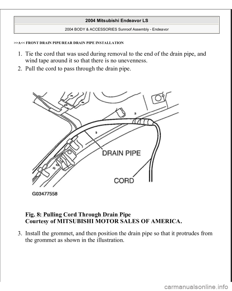
>>A<< FRONT DRAIN PIPE/REAR DRAIN PIPE INSTALLATION1. Tie the cord that was used during removal to the end of the drain pipe, and
wind tape around it so that there is no unevenness.
2. Pull the cord to pass through the drain pipe.
Fig. 8: Pulling Cord Through Drain Pipe
Courtesy of MITSUBISHI MOTOR SALES OF AMERICA.
3. Install the grommet, and then position the drain pipe so that it protrudes from
the grommet as shown in the illustration.
2004 Mitsubishi Endeavor LS
2004 BODY & ACCESSORIES Sunroof Assembly - Endeavor
Page 3572 of 3870
MITSUBISHI
3.8L V6 - SOHC - Endeavor & Galant
MANUFACTURER'S SUGGESTED SCHEDULED MAINTENANCE Manufacturer recommends the belt be replaced every 60,000 miles except in
California, Massachusetts and Vermont. In California, Massachusetts and Vermont,
timing belt replacement is recommended, but not required, at 60,000 miles. In these
states, replace timing belt at 105,000 miles, unless previously changed. REMOVAL & INSTALLATION TIMING BELT Removal 1. On Galant, remove engine cover. On all models, remove skid plate and under
cover. Remove accessory drive belts. Using Pulley Holder (MB991800) and
Pins "B" (MB001802), remove crankshaft pulley.
2. Disconnect harness connectors on connector bracket. See Fig. 1
or Fig. 2
.
Remove connector bracket. Remove engine mount support bracket. Remove
both upper timing belt covers.
3. Remove tensioner pulley and tensioner bracket. Remove crankshaft position
sensor harness clamp. Remove lower timing belt cover. Remove front engine
mount and front engine mount bracket.
4. Turn crankshaft clockwise to align camshaft and crankshaft timing marks. See
Fig. 3
. If timing belt is to be reused, place arrow on belt to indicate direction
of belt rotation.
5. Loosen belt tensioner
pulle
y center bolt. Remove timin
g belt. Remove timin
g CAUTION: This application is an interference engine. Do not
rotate camshaft or crankshaft when timing belt is
removed, or engine damage may occur.
CAUTION: Always turn crankshaft in clockwise direction (as
viewed from front of engine).
2004 Mitsubishi Endeavor Limited MITSUBISHI 3.8L V6 - SOHC - Endeavor & Galant
2004 Mitsubishi Endeavor Limited MITSUBISHI 3.8L V6 - SOHC - Endeavor & Galant