2004 MITSUBISHI ENDEAVOR lock
[x] Cancel search: lockPage 298 of 3870
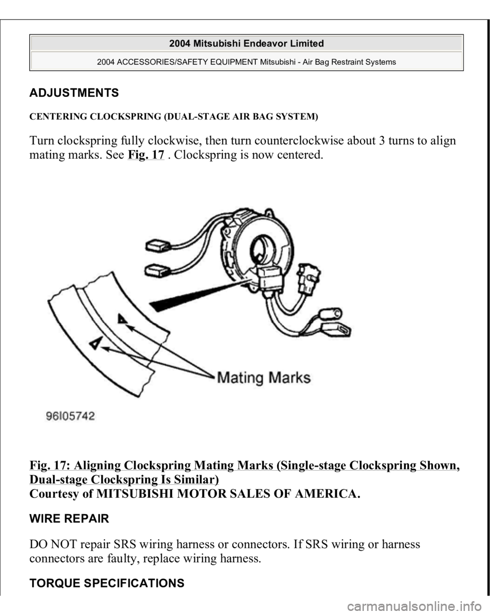
ADJUSTMENTS CENTERING CLOCKSPRING (DUAL-STAGE AIR BAG SYSTEM) Turn clockspring fully clockwise, then turn counterclockwise about 3 turns to align
mating marks. See Fig. 17
. Clockspring is now centered.
Fig. 17: Aligning Clockspring Mating Marks (Single
-sta
ge Clocks
prin
g Shown,
Dual
-stage Clockspring Is Similar)
Courtesy of MITSUBISHI MOTOR SALES OF AMERICA.
WIRE REPAIR DO NOT repair SRS wiring harness or connectors. If SRS wiring or harness
connectors are faulty, replace wiring harness. TORQUE SPECIFICATION
S
2004 Mitsubishi Endeavor Limited
2004 ACCESSORIES/SAFETY EQUIPMENT Mitsubishi - Air Bag Restraint Systems
Page 299 of 3870
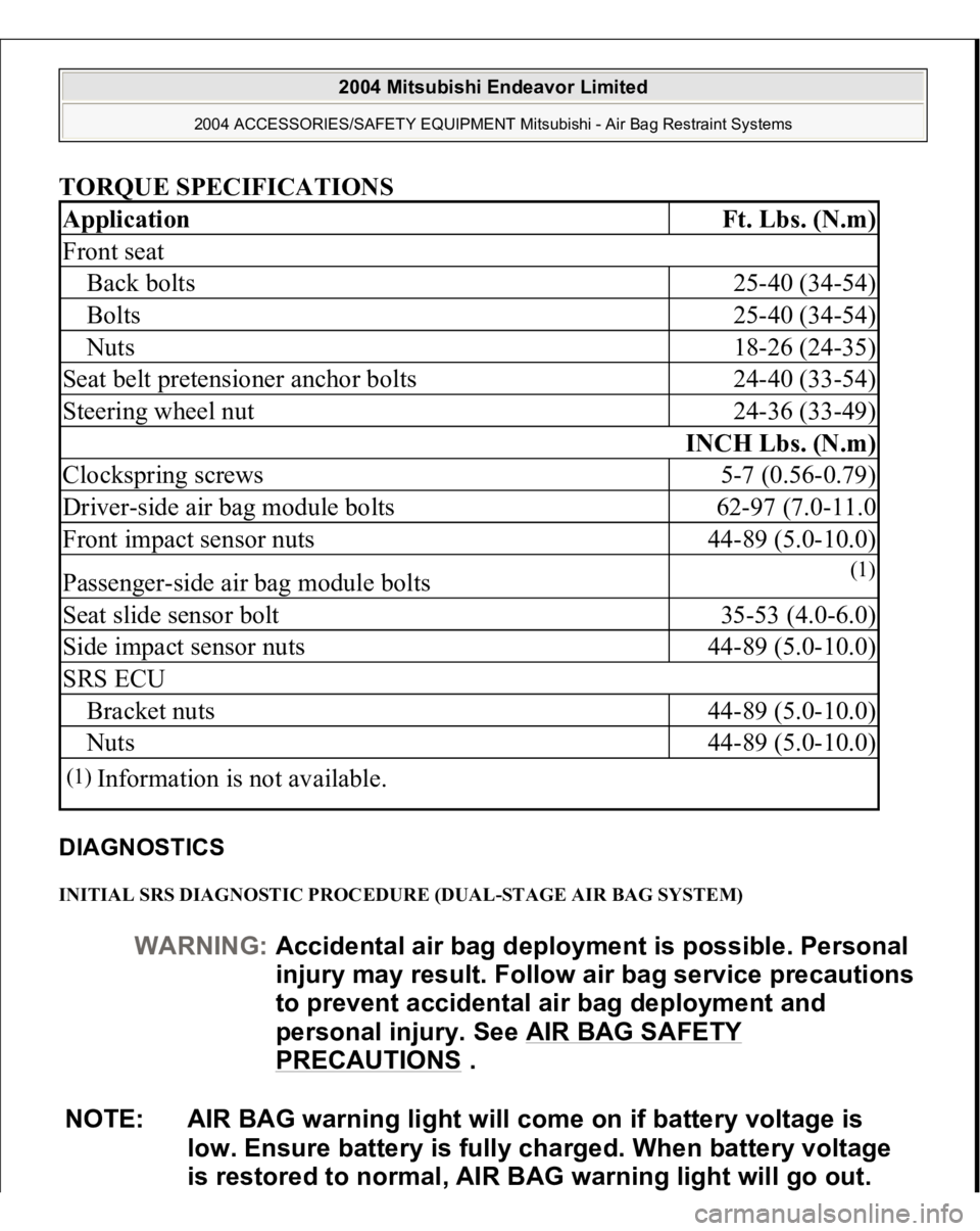
TORQUE SPECIFICATIONS DIAGNOSTICS INITIAL SRS DIAGNOSTIC PROCEDURE (DUAL-STAGE AIR BAG SYSTEM) Application
Ft. Lbs. (N.m)
Front seatBack bolts
25-40 (34-54)
Bolts
25-40 (34-54)
Nuts
18-26 (24-35)
Seat belt pretensioner anchor bolts
24-40 (33-54)
Steering wheel nut
24-36 (33-49)
INCH Lbs. (N.m)
Clockspring screws
5-7 (0.56-0.79)
Driver-side air bag module bolts
62-97 (7.0-11.0
Front impact sensor nuts
44-89 (5.0-10.0)
Passenger-side air bag module bolts
(1)
Seat slide sensor bolt
35-53 (4.0-6.0)
Side impact sensor nuts
44-89 (5.0-10.0)
SRS ECUBracket nuts
44-89 (5.0-10.0)
Nuts
44-89 (5.0-10.0)
(1)
Information is not available.
WARNING:Accidental air bag deployment is possible. Personal
in
jury ma
y result. Follow air ba
g service precautions
to prevent accidental air bag deployment and
personal injury. See AIR BAG SAFETY
PRECAUTIONS
.
NOTE: AIR BAG warning light will come on if battery voltage is
low. Ensure battery is fully charged. When battery voltage
is restored to normal, AIR BAG warning light will go out.
2004 Mitsubishi Endeavor Limited
2004 ACCESSORIES/SAFETY EQUIPMENT Mitsubishi - Air Bag Restraint Systems
Page 303 of 3870
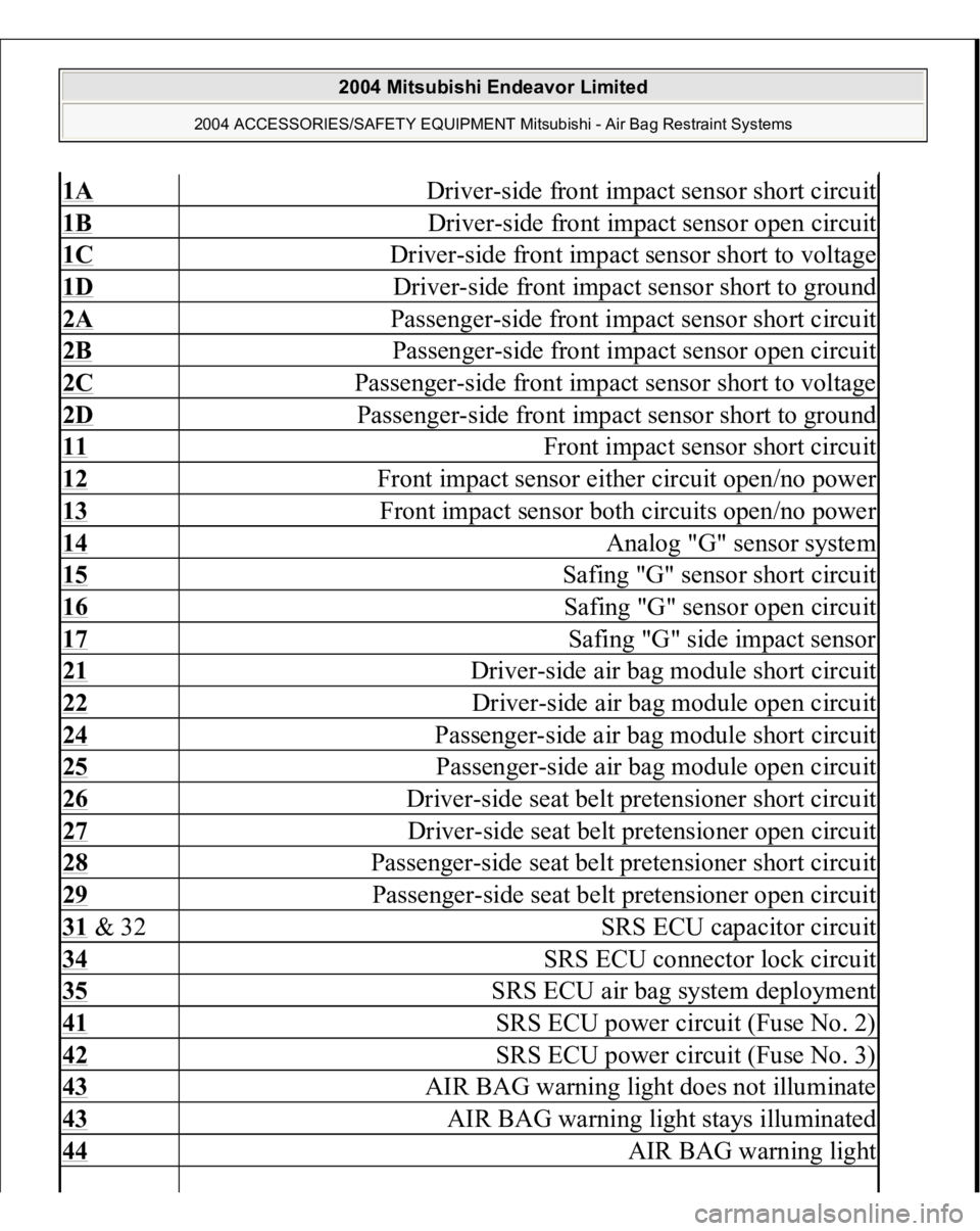
1A
Driver-side front impact sensor short circuit
1B
Driver-side front impact sensor open circuit
1C
Driver-side front impact sensor short to voltage
1D
Driver-side front impact sensor short to ground
2A
Passenger-side front impact sensor short circuit
2B
Passenger-side front impact sensor open circuit
2C
Passenger-side front impact sensor short to voltage
2D
Passenger-side front impact sensor short to ground
11
Front impact sensor short circuit
12
Front impact sensor either circuit open/no power
13
Front impact sensor both circuits open/no power
14
Analog "G" sensor system
15
Safing "G" sensor short circuit
16
Safing "G" sensor open circuit
17
Safing "G" side impact sensor
21
Driver-side air bag module short circuit
22
Driver-side air bag module open circuit
24
Passenger-side air bag module short circuit
25
Passenger-side air bag module open circuit
26
Driver-side seat belt pretensioner short circuit
27
Driver-side seat belt pretensioner open circuit
28
Passenger-side seat belt pretensioner short circuit
29
Passenger-side seat belt pretensioner open circuit
31 & 32
SRS ECU capacitor circuit
34
SRS ECU connector lock circuit
35
SRS ECU air bag system deployment
41
SRS ECU power circuit (Fuse No. 2)
42
SRS ECU power circuit (Fuse No. 3)
43
AIR BAG warning light does not illuminate
43
AIR BAG warning light stays illuminated
44
AIR BAG warning light
2004 Mitsubishi Endeavor Limited
2004 ACCESSORIES/SAFETY EQUIPMENT Mitsubishi - Air Bag Restraint Systems
Page 307 of 3870
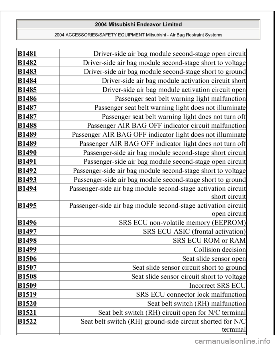
B1481
Driver-side air bag module second-stage open circuit
B1482
Driver-side air bag module second-stage short to voltage
B1483
Driver-side air bag module second-stage short to ground
B1484
Driver-side air bag module activation circuit short
B1485
Driver-side air bag module activation circuit open
B1486
Passenger seat belt warning light malfunction
B1487
Passenger seat belt warning light does not illuminate
B1487
Passenger seat belt warning light does not turn of
f
B1488
Passenger AIR BAG OFF indicator circuit malfunction
B1489
Passenger AIR BAG OFF indicator light does not illuminate
B1489
Passenger AIR BAG OFF indicator light does not turn of
f
B1490
Passenger-side air bag module second-stage short circuit
B1491
Passenger-side air bag module second-stage open circuit
B1492
Passenger-side air bag module second-stage short to voltage
B1493
Passenger-side air bag module second-stage short to ground
B1494
Passenger-side air bag module second-stage activation circuit
short circuit
B1495
Passenger-side air bag module second-stage activation circuit
open circuit
B1496
SRS ECU non-volatile memory (EEPROM)
B1497
SRS ECU ASIC (frontal activation)
B1498
SRS ECU ROM or RAM
B1499
Collision decision
B1506
Seat slide sensor open
B1507
Seat slide sensor circuit short to ground
B1508
Seat slide sensor circuit short to voltage
B1509
Incorrect SRS ECU
B1519
SRS ECU connector lock malfunction
B1520
Seat belt switch (RH) malfunction
B1521
Seat belt switch (RH) circuit open for N/C terminal
B1522
Seat belt switch (RH) ground-side circuit shorted for N/C
terminal
2004 Mitsubishi Endeavor Limited
2004 ACCESSORIES/SAFETY EQUIPMENT Mitsubishi - Air Bag Restraint Systems
Page 317 of 3870
DTC 21: DRIVE
R-SIDE AIR BAG MODULE SHORT CIRCUIT
1. Before proceeding, see AIR BAG SAFETY PRECAUTIONS
. If DTC 34 is
retrieved, go to next step. If DTC 34 is not retrieved, go to step 3 .
2. Inspect SRS ECU connector C-26. See SRS ELECTRONIC CONTROL
UNIT (SRS ECU)
under REMOVAL & INSTALLATION. See Fig. 19
. If
SRS ECU connector C-26 is connected correctly, go to next step. If SRS ECU
connector is not connected properly, install connector correctly. Go to step 8 .
3. Disconnect negative battery cable. Disconnect, then reconnect SRS ECU
connector C-26, lower clockspring connector C-307 and driver-side air bag
module connector C-305. See DRIVER
-SIDE AIR BAG MODULE &
CLOCKSPRING
under REMOVAL & INSTALLATION. Connect negative
battery cable. Using scan tool, erase then retrieve DTCs. If DTC 21 is
retrieved, go to next step. If DTC 21 is not retrieved, system is normal at this
time.
4. Disconnect negative battery cable. Connect Resistor Harness (MB991866) to
terminals of upper clockspring connector C-306 by backprobing connector.
Connect Load Resistor (MB991865) to resistor harness. Connect negative
battery cable. Using scan tool, erase then retrieve DTCs. If DTC 21 is
retrieved, go to next step. If DTC 21 is not retrieved, replace driver-side air bag
module. Go to step 8 .
5. Disconnect negative battery cable. Connect resistor harness and load resistor to
terminals No. 3 and 4 of clockspring connector C-307 by backprobing
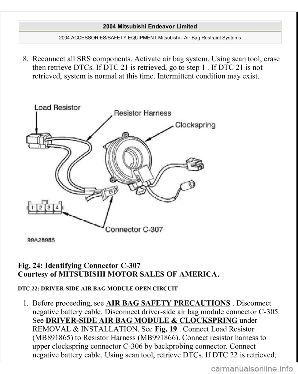
connector. See Fig. 24
. Connect negative battery cable. Using scan tool, erase
then retrieve DTCs. If DTC 21 is retrieved, go to next step. If DTC 21 is not
retrieved, replace clockspring. Go to step 8 .
6. Disconnect SRS ECU connector C-26 and clockspring connector C-307. Insert
a cable tie or similar insulator between terminals No. 11 (Yellow/Black wire)
and No. 12 (Yellow wire) of SRS ECU connector to release shorting bar. See
Fig. 21
. Check for continuity between terminals No. 11 and 12. If continuity
exists, go to next step. If continuity does not exist, erase, then retrieve DTCs
using scan tool. If DTC 21 is retrieved, replace SRS ECU. Go to step 8 .
7. Check wire harness between SRS ECU connector C-26 and lower clockspring
connector C-307 for a short circuit. If wire harness is okay, go to next step. If
wire harness has a short circuit, replace wire harness. Go to next step
2004 Mitsubishi Endeavor Limited
2004 ACCESSORIES/SAFETY EQUIPMENT Mitsubishi - Air Bag Restraint Systems
Page 318 of 3870
8. Reconnect all SRS components. Activate air bag system. Using scan tool, erase
then retrieve DTCs. If DTC 21 is retrieved, go to step 1 . If DTC 21 is not
retrieved, system is normal at this time. Intermittent condition may exist.
Fig. 24: Identifying Connector C
-307
Courtesy of MITSUBISHI MOTOR SALES OF AMERICA.
DTC 22: DRIVER-SIDE AIR BAG MODULE OPEN CIRCUIT 1. Before proceeding, see AIR BAG SAFETY PRECAUTIONS
. Disconnect
negative battery cable. Disconnect driver-side air bag module connector C-305.
See DRIVER
-SIDE AIR BAG MODULE & CLOCKSPRING
under
REMOVAL & INSTALLATION. See Fig. 19
. Connect Load Resistor
(MB891865) to Resistor Harness (MB991866). Connect resistor harness to
upper clockspring connector C-306 by backprobing connector. Connect
negative battery cable. Using scan tool, retrieve DTCs. If DTC 22 is retrieved,
2004 Mitsubishi Endeavor Limited
2004 ACCESSORIES/SAFETY EQUIPMENT Mitsubishi - Air Bag Restraint Systems
Page 319 of 3870
go to next step. If DTC 22 is not retrieved, replace driver-side air bag module.
Go to step 4 .
2. Disconnect negative battery cable. Disconnect clockspring connector C-307.
Connect resistor harness to clockspring connector C-307 by backprobing
connector terminals No. 3 and 4. See Fig. 24
. Connect negative battery cable.
Using scan tool, erase then retrieve DTCs. If DTC 22 is retrieved, go to next
step. If DTC 22 is not retrieved, replace clockspring. Go to step 4 .
3. Disconnect SRS ECU connector C-26 and clockspring connector C-307. See
SRS ELECTRONIC CONTROL UNIT (SRS ECU)
under REMOVAL &
INSTALLATION. Measure resistance between connector C-26, terminal No.
11 (Yellow/Black wire) and clockspring connector C-307, terminal No. 3.
Measure resistance between connector C-26, terminal No. 12 (Yellow wire)
and clockspring connector C-307, terminal No. 4. If resistance is less than 2
ohms in each circuit, recheck for DTCs. If DTC 22 is retrieved, replace SRS
ECU. Go to next step. If resistance is more than 2 ohms in either wire, replace
wire harness between SRS ECU and clockspring. Go to next step.
4. Reconnect all SRS components. Activate air bag system. Using scan tool, erase
then retrieve DTCs. If DTC 22 is retrieved, go to step 1 . If DTC 22 is not
retrieved, system is normal at this time. Intermittent condition may exist.
DTC 24: PASSENGER-SIDE AIR BAG MODULE SHORT CIRCUIT 1. Before proceeding, see AIR BAG SAFETY PRECAUTIONS
. Disable air
bag system. See DISABLING & ACTIVATING AIR BAG SYSTEM
. If
DTC 34 is retrieved, go to next step. If DTC 34 is not retrieved, go to step 3 .
2. Inspect SRS ECU connector C-26. See SRS ELECTRONIC CONTROL
UNIT (SRS ECU)
under REMOVAL & INSTALLATION. See Fig. 19
. If
connector is not connected properly, connect properly. Go to step 7 . If
connector is connected properly, go to next step.
3. Disconnect negative battery cable. Disconnect, then reconnect passenger-side
air bag module connector C-09 and SRS ECU connector C-26. See
PASSENGER
-SIDE AIR BAG MODULE
under REMOVAL &
INSTALLATION. Connect negative battery cable. Using scan tool, erase then
retrieve DTCs. If DTC 24 is retrieved, go to next step. If DTC 24 is not
retrieved, s
ystem is normal at this time.
2004 Mitsubishi Endeavor Limited
2004 ACCESSORIES/SAFETY EQUIPMENT Mitsubishi - Air Bag Restraint Systems
Page 325 of 3870
BELT PRETENSIONE
R under REMOVAL & INSTALLATION. See Fig.
19 . Connect Load Resistor (MB991865) to Resistor Harness (MB991884).
Connect resistor harness to passenger-side seat belt pretensioner connector.
Connect negative battery cable. Using scan tool, check for DTCs. If DTC 29 is
retrieved, go to next step. If DTC 29 is not retrieved, replace passenger-side
seat belt pretensioner. Go to step 4 .
3. Disconnect SRS ECU connector C-25. See SRS ELECTRONIC CONTROL UNIT (SRS ECU)
under REMOVAL & INSTALLATION. Measure
resistance of Red wire between SRS ECU connector C-25, terminal No. 27 and
driver-side seat belt pretensioner connector D-32, terminal No. 1. See Fig. 25
.
Measure resistance of Red/White wire between SRS ECU connector terminal
No. 28 and driver-side seat belt pretensioner connector D-32, terminal No. 2. If
resistance is 2 ohms or less in both wires, erase, then retrieve DTCs using scan
tool. If DTC 29 is retrieved, replace SRS ECU. If resistance is more than 2
ohms in either wire, replace wire harness between SRS ECU and seat belt
pretensioner.
4. Reconnect all SRS components. Activate air bag system. Using scan tool, erase
then retrieve DTCs. If DTC 29 is retrieved, go to step 1 . If DTC 29 is not
retrieved, system is normal at this time. Intermittent condition may exist.
DTC 31 & 32: SRS ECU CAPACITOR If DTC 31 or 32 is present, replace SRS ECU. See SRS ELECTRONIC CONTROL UNIT (SRS ECU)
under REMOVAL & INSTALLATION.
DTC 34: SRS ECU CONNECTOR LOCK CIRCUIT 1. Before proceeding, see AIR BAG SAFETY PRECAUTIONS
. Check SRS-
ECU connectors C-25 and C-26. See SRS ELECTRONIC CONTROL UNIT
(SRS ECU)
under REMOVAL & INSTALLATION. See Fig. 19
. If
connectors are connected properly, go to next step. If connectors are not
connected properly, connect properly. Go to step 3 .
2. Disconnect and inspect connectors C-25 and C-26. If connectors are damaged,
replace wire harness. Go to next step. If connectors are not damaged, reconnect
connectors. Using scan tool, erase then retrieve DTCs. If DTC 34 is retrieved,
re
place SRS ECU. Go to next ste
p.
2004 Mitsubishi Endeavor Limited
2004 ACCESSORIES/SAFETY EQUIPMENT Mitsubishi - Air Bag Restraint Systems