Page 271 of 3870
2. With the ignition switch turned to the "ON" position, read the voltage between
terminals number 2 and number 3.
Standard Value: 2.4 - 2.6 V
3. With special tool MB991348 connected, rotate so that the arrow points straight
down. Read output voltage between terminals number 2 and number 3.
Standard Value: 3.4 - 3.6 V
4. If the voltage deviates from the standard value, check the power supply wire
and ground wire. If no problems are found, replace the G-sensor. SPECIFICATIONS FASTENER TIGHTENING SPECIFICATION FASTENER TIGHTENING SPECIFICATION GENERAL SPECIFICATIONS Fig. 166: General Specifications
Courtesy of MITSUBISHI MOTOR SALES OF AMERICA.
SERVICE SPECIFICATION ITEM
SPECIFICATION
Brake tube flare nut
15 +/- 2 N.m (12 +/- 1 ft-lb)
2004 Mitsubishi Endeavor LS
2004 BRAKES Anti-Lock Braking System (ABS) - Endeavor
Page 272 of 3870
Fig. 167: Service Specificatio
n
Courtesy of MITSUBISHI MOTOR SALES OF AMERICA.
2004 Mitsubishi Endeavor LS
2004 BRAKES Anti-Lock Braking System (ABS) - Endeavor
Page 276 of 3870

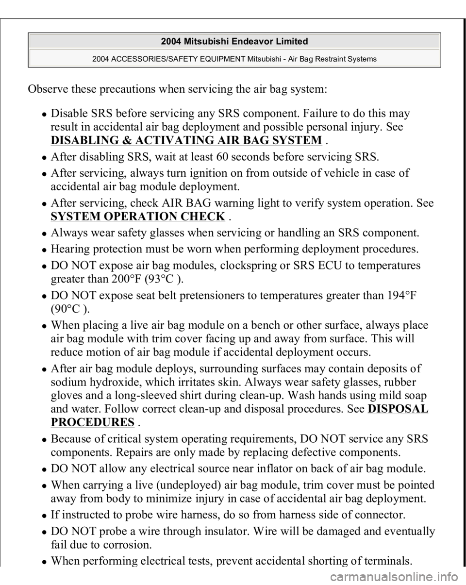
Observe these precautions when servicing the air bag system:
Disable SRS before servicing any SRS component. Failure to do this may
result in accidental air bag deployment and possible personal injury. See DISABLING & ACTIVATING AIR BAG SYSTEM
.
After disabling SRS, wait at least 60 seconds before servicing SRS. After servicing, always turn ignition on from outside of vehicle in case of
accidental air bag module deployment. After servicing, check AIR BAG warning light to verify system operation. See SYSTEM OPERATION CHECK
.
Always wear safety glasses when servicing or handling an SRS component. Hearing protection must be worn when performing deployment procedures. DO NOT expose air bag modules, clockspring or SRS ECU to temperatures
greater than 200°F (93°C ). DO NOT expose seat belt pretensioners to temperatures greater than 194°F
(90°C ). When placing a live air bag module on a bench or other surface, always place
air bag module with trim cover facing up and away from surface. This will
reduce motion of air bag module if accidental deployment occurs. After air bag module deploys, surrounding surfaces may contain deposits of
sodium hydroxide, which irritates skin. Always wear safety glasses, rubber
gloves and a long-sleeved shirt during clean-up. Wash hands using mild soap
and water. Follow correct clean-up and disposal procedures. See
DISPOSAL
PROCEDURES
.
Because of critical system operating requirements, DO NOT service any SRS
components. Repairs are only made by replacing defective components. DO NOT allow any electrical source near inflator on back of air bag module. When carrying a live (undeployed) air bag module, trim cover must be pointed
away from body to minimize injury in case of accidental air bag deployment. If instructed to probe wire harness, do so from harness side of connector. DO NOT probe a wire through insulator. Wire will be damaged and eventually
fail due to corrosion. When
performin
g electrical tests,
prevent accidental shortin
g of terminals.
2004 Mitsubishi Endeavor Limited
2004 ACCESSORIES/SAFETY EQUIPMENT Mitsubishi - Air Bag Restraint Systems
Page 294 of 3870
slide sensor.
3. To install, reverse removal procedure. Tighten seat slide sensor bolt and front
seat bolts to specification. See TORQUE SPECIFICATIONS
. Activate air
bag system.
Fig. 13: Identifying Seat Slide Sensor
Courtesy of MITSUBISHI MOTOR SALES OF AMERICA.
SIDE IMPACT AIR BAG MODULE Removal & Installation 1. Before proceeding, see AIR BAG SAFETY PRECAUTIONS
. Disable air
bag system. See DISABLING & ACTIVATING AIR BAG SYSTEM
.
2. Disconnect wiring under appropriate front seat. Remove seat nuts and bolts.
Remove seat from vehicle. Remove bolts securing seat back assembly to seat
recliner hin
ges. Remove front seat back assembl
y.
NOTE: Side impact air bag module is replaced with seat back
assembly and cannot be serviced separately.
2004 Mitsubishi Endeavor Limited
2004 ACCESSORIES/SAFETY EQUIPMENT Mitsubishi - Air Bag Restraint Systems
Page 299 of 3870

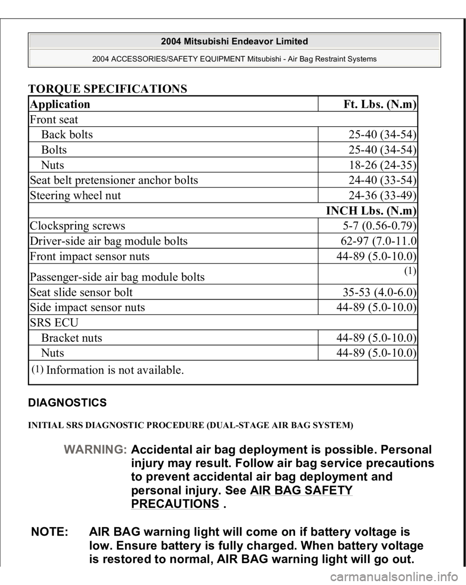
TORQUE SPECIFICATIONS DIAGNOSTICS INITIAL SRS DIAGNOSTIC PROCEDURE (DUAL-STAGE AIR BAG SYSTEM) Application
Ft. Lbs. (N.m)
Front seatBack bolts
25-40 (34-54)
Bolts
25-40 (34-54)
Nuts
18-26 (24-35)
Seat belt pretensioner anchor bolts
24-40 (33-54)
Steering wheel nut
24-36 (33-49)
INCH Lbs. (N.m)
Clockspring screws
5-7 (0.56-0.79)
Driver-side air bag module bolts
62-97 (7.0-11.0
Front impact sensor nuts
44-89 (5.0-10.0)
Passenger-side air bag module bolts
(1)
Seat slide sensor bolt
35-53 (4.0-6.0)
Side impact sensor nuts
44-89 (5.0-10.0)
SRS ECUBracket nuts
44-89 (5.0-10.0)
Nuts
44-89 (5.0-10.0)
(1)
Information is not available.
WARNING:Accidental air bag deployment is possible. Personal
in
jury ma
y result. Follow air ba
g service precautions
to prevent accidental air bag deployment and
personal injury. See AIR BAG SAFETY
PRECAUTIONS
.
NOTE: AIR BAG warning light will come on if battery voltage is
low. Ensure battery is fully charged. When battery voltage
is restored to normal, AIR BAG warning light will go out.
2004 Mitsubishi Endeavor Limited
2004 ACCESSORIES/SAFETY EQUIPMENT Mitsubishi - Air Bag Restraint Systems
Page 535 of 3870
Fig. 79: Using Special Tools And Tightening Jam Nut
Courtesy of MITSUBISHI MOTOR SALES OF AMERICA.
27. Move the output shaft to measure the end play and record the measurement
value.
28. Remove the parts that were installed in steps 21 to 25.
29. Add 1.88 mm (0.074 inch)* and 0.01 to 0.09 mm (0.0004 to 0.0035 inch)** to
the measured value in step 26 and select a spacer of the same thickness.
Adjustment spacer sizes are all listed on SERVICE SPECIFICATIONS
.
Select the most suitable one from among those listed.
30. Repeat steps 22 to 25 again, installing each part and using the appropriate
NOTE: *is the thickness of the spacer installed in step 21. **is
the preload of the output shaft.
2004 Mitsubishi Endeavor XLS
2004 TRANSMISSION Automatic Transaxle Overhaul - Endeavor
Page 578 of 3870
Fig. 123: Identifying Torque Converter Housing Mounting Bolts
Courtesy of MITSUBISHI MOTOR SALES OF AMERICA.
79. Use a micrometer to measure the thickness of the crushed solder beads and
record the measured value. Add 0.045 to 0.105 mm (0.0018 to 0.0041 inch)* to
the measured value and select a spacer with the corresponding thickness.
Adjustment spacer sizes are all listed on SERVICE SPECIFICATIONS
.
Select the most suitable one from among those listed.
NOTE: *is the thickness for the differential case preload.
2004 Mitsubishi Endeavor XLS
2004 TRANSMISSION Automatic Transaxle Overhaul - Endeavor
Page 602 of 3870
Fig. 148: Identifying Oil Seal Installer
Courtesy of MITSUBISHI MOTOR SALES OF AMERICA.
ASSEMBLY SERVICE POINTS >>A<< OIL SEAL INSTALLATION 1. Apply a small amount of ATF to the oil seal lip.
2. Use special tool MD998334 to tap the oil seal in the oil pump body.
2004 Mitsubishi Endeavor XLS
2004 TRANSMISSION Automatic Transaxle Overhaul - Endeavor