2004 MITSUBISHI ENDEAVOR instrument panel
[x] Cancel search: instrument panelPage 394 of 3870
1. Connect scan tool to Data Link Connector (DLC). See INITIAL SRS
DIAGNOSTIC PROCEDURE
under DIAGNOSTICS. If scan tool is able to
diagnose CAN bus lines and CAN bus lines are satisfactory, go to next step. If
scan tool cannot diagnose CAN bus lines, repair CAN bus lines. Go to next
step.
2. Erase, then retrieve DTCs. If DTC B1475 is retrieved, replace SRS ECU. See
SRS ELECTRONIC CONTROL UNIT (SRS ECU)
under REMOVAL &
INSTALLATION. If DTC B1475 is not retrieved, an intermittent condition
may exist.
DTCB1476: POWER SUPPLY VOLTAGE DROPS ABNORMALLY 1. Connect scan tool to Data Link Connector (DLC). See INITIAL SRS
DIAGNOSTIC PROCEDURE
under DIAGNOSTICS. If scan tool is able to
diagnose CAN bus lines and CAN bus lines are satisfactory, go to next step. If
scan tool cannot diagnose CAN bus lines, repair CAN bus lines. Go to next
step.
2. Erase, then retrieve DTCs. Turn ignition off. If DTC B1476 is retrieved, go to
next step. If DTC B1476 is not retrieved, an intermittent condition may exist.
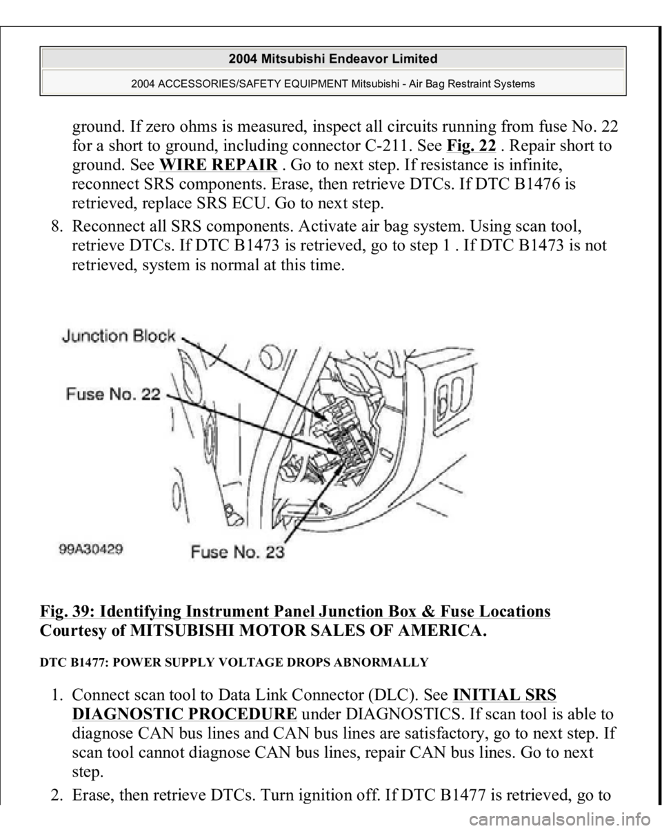
3. Remove fuse No. 22 from instrument panel junction block. See Fig. 39
. If fuse
is blown, go to step 6 . If fuse is not blown, go to next step.
4. Disconnect negative battery cable. Disconnect SRS ECU connector C-26. See
SRS ELECTRONIC CONTROL UNIT (SRS ECU)
under REMOVAL &
INSTALLATION. See Fig. 30
. Connect negative battery cable. Turn ignition
on. Measure voltage between ground and SRS ECU connector C-26, terminal
No. 23 (Black/White wire). If voltage is 9 volts or more, reconnect SRS
components. Erase, then retrieve DTCs. If DTC B1476 is retrieved, replace
SRS ECU. Go to step 8 . If DTC B1476 is not retrieved, go to next step.
5. Inspect Black/White wire between SRS ECU connector C-26, terminal No. 23
and ignition switch connector C-308, terminal No. 2. If wire is okay, go to step
8 . If wire is not okay, replace harness between SRS ECU and ignition switch.
Go to step 8 .
6. Replace fuse. Turn ignition on for one minute, then turn off. Inspect fuse. If
fuse is okay, go to step 8 . If fuse is not okay, go to next step.
7. Measure resistance between SRS ECU connector C-26
, terminal No. 23 and
2004 Mitsubishi Endeavor Limited
2004 ACCESSORIES/SAFETY EQUIPMENT Mitsubishi - Air Bag Restraint Systems
Page 395 of 3870
ground. If zero ohms is measured, inspect all circuits running from fuse No. 22
for a short to ground, including connector C-211. See Fig. 22
. Repair short to
ground. See WIRE REPAIR
. Go to next step. If resistance is infinite,
reconnect SRS components. Erase, then retrieve DTCs. If DTC B1476 is
retrieved, replace SRS ECU. Go to next step.
8. Reconnect all SRS components. Activate air bag system. Using scan tool,
retrieve DTCs. If DTC B1473 is retrieved, go to step 1 . If DTC B1473 is not
retrieved, system is normal at this time.
Fig. 39: Identifying Instrument Panel Junction Box & Fuse Locations
Courtesy of MITSUBISHI MOTOR SALES OF AMERICA.
DTC B1477: POWER SUPPLY VOLTAGE DROPS ABNORMALLY 1. Connect scan tool to Data Link Connector (DLC). See INITIAL SRS
DIAGNOSTIC PROCEDURE
under DIAGNOSTICS. If scan tool is able to
diagnose CAN bus lines and CAN bus lines are satisfactory, go to next step. If
scan tool cannot diagnose CAN bus lines, repair CAN bus lines. Go to next
step.
2. Erase, then retrieve DTCs. Turn ignition off. If DTC B1477 is retrieved,
go to
2004 Mitsubishi Endeavor Limited
2004 ACCESSORIES/SAFETY EQUIPMENT Mitsubishi - Air Bag Restraint Systems
Page 396 of 3870
next step. If DTC B1477 is not retrieved, an intermittent condition may exist.
3. Remove fuse No. 23 from instrument panel junction block. See Fig. 39
. If fuse
is blown, go to step 6 . If fuse is not blown, go to next step.
4. Disconnect negative battery cable. Disconnect SRS ECU connector C-26. See
SRS ELECTRONIC CONTROL UNIT (SRS ECU)
under REMOVAL &
INSTALLATION. See Fig. 30
. Connect negative battery cable. Turn ignition
on. Measure voltage between ground and SRS ECU connector C-26, terminal
No. 24 (Black/Yellow wire). If voltage is 9 volts or more, reconnect SRS
components. Erase, then retrieve DTCs. If DTC B1477 is retrieved, replace
SRS ECU. Go to step 8 . If DTC B1477 is not retrieved, go to next step.
5. Inspect Black/Yellow wire between SRS ECU connector C-26, terminal No. 24
and ignition switch connector C-308, terminal No. 2. See WIRING
DIAGRAMS
. If wire is okay, go to step 8 . If wire is not okay, replace
harness between SRS ECU and ignition switch. Go to step 8 .
6. Replace fuse. Turn ignition on for one minute, then turn off. Inspect fuse. If
fuse is okay, go to step 8 . If fuse is not okay, go to next step.
7. Measure resistance between SRS ECU connector terminal No. 24 and ground.
If zero ohms is measured, inspect all circuits running from fuse No. 23 for a
short to ground. including connector C-211. See Fig. 22
. Repair short to
ground. See WIRE REPAIR
. Go to next step. If continuity does not exist,
reconnect SRS components. Erase, then retrieve DTCs. If DTC B1477 is
retrieved, replace SRS ECU. Go to next step.
8. Reconnect all SRS components. Activate air bag system. Using scan tool,
retrieve DTCs. If DTC B1473 is retrieved, go to step 1 . If DTC B1473 is not
retrieved, system is normal at this time.
DTC B1478: SRS ECU CAPACITOR CIRCUIT VOLTAGE HIGH 1. Connect scan tool to Data Link Connector (DLC). See INITIAL SRS
DIAGNOSTIC PROCEDURE
under DIAGNOSTICS. If scan tool is able to
diagnose CAN bus lines and CAN bus lines are satisfactory, go to next step. If
scan tool cannot diagnose CAN bus lines, repair CAN bus lines. Go to next
step.
2. Erase, then retrieve DTCs. If DTC B1478 is retrieved, replace SRS ECU. See
SRS ELECTRONIC CONTROL UNIT (SRS ECU)
under REMOVAL &
2004 Mitsubishi Endeavor Limited
2004 ACCESSORIES/SAFETY EQUIPMENT Mitsubishi - Air Bag Restraint Systems
Page 1100 of 3870
GROUNDS GROUNDS LOCATION C13 (Black, 32 Pin)
Behind right kick panel.Fig. 76
.
C15 (2 Pin)
Behind right end of dash.Fig. 76
.
C24 (11 Pin)
Under front of center console.Fig. 76
.
C29 (Black, 32 pin)
Behind left kick panel.Fig. 76
.
C30 (43 Pin)
Behind left end of dash.Fig. 76
.
C31 (38 Pin)
Behind left end of dash.Fig. 76
.
C32 (16 Pin)
Behind left end of dash. See Fig. 76
.
C33 (6 Pin)
Behind left end of dash. See Fig. 76
.
D20 (Gray, 3 Pin)
Front of left rear wheelwell.Fig. 80
.
D22 (10 Pin)
Left "B" pillar.Fig. 80
.
D34 (10 Pin)
Right "B" pillar.Fig. 80
.
F02 (11 Pin)
Upper left corner of liftgate. See Fig. 88
.
F03 (1 Pin)
Upper left corner of liftgate. See Fig. 88
.
Component
Location
G1
Right side of engine compartment. See Fig. 20
.
G2
Right side of engine compartment.Fig. 20
.
G3
Left rear of engine compartment.Fig. 21
.
G4
Behind upper center of dash.Fig. 22
.
G5
Behind upper center of dash.Fig. 23
.
G6
Front center of roof.Fig. 24
.
G7
Behind instrument cluster.Fig. 25
.
G8
Behind lower center of dash.Fig. 26
.
G9
Center of liftgate.Fig. 27
.
G10
Front of engine compartment.Fig. 28
.
G11
Front of engine compartment.Fig. 28
.
G12
Left front of engine compartment.Fig. 29
.
G13
Near engine compartment relay box.Fig. 30
.
G14
Under right front seat.Fig. 31
.
2004 Mitsubishi Endeavor LS
2004 MITSUBISHI Endeavor
Page 1636 of 3870
Q: Is the wiring harness between radio and CD player or radio, CD player
and CD changer connector C-105 (terminal 20) and ignition switch (ACC)
in good condition?
YES: Go to Step 4.
NO: Repair the wiring harness. If the power switch is turned on, the radio
and CD player or radio, CD player and CD changer should operate
normally.
STEP 4. Check the installation condition of the radio and CD player or
radio, CD player and CD changer.
Q: Are the radio and CD player or radio, CD player and CD changer
installed correctly?
YES: Repair or replace the radio and CD player or radio, CD player and
CD changer. If the power switch is turned on, the radio and CD player or
radio, CD player and CD changer should operate normally.
NO: Install the radio and CD player or radio, CD player and CD changer
properly. If the power switch is turned on, the radio and CD player or
radio, CD player and CD changer should operate normally.
STEP 5. Measure at radio and CD player or radio, CD player and CD
changer connector C-105 in order to check the battery circuit of power
supply system to the radio and CD player or radio, CD player and CD
changer (ignition switch ACC).
1. Disconnect radio and CD player or radio, CD player and CD changer
connector
C-105, and measure at the wiring harness side.
NOTE: The radio and CD player or radio, CD player and CD
changer are grounded to the instrument panel center
reinforcement directly.
2004 Mitsubishi Endeavor LS
2004 BODY & ACCESSORIES Radio With Tape Player & Cd Player - Endeavor
Page 1642 of 3870
Q: Is the wiring harness between radio and CD player or radio, CD player
and CD changer connector C-105 (terminal 20) and ignition switch (ACC)
in good condition?
YES: There is no action to be taken.
NO: Repair the wiring harness. If the power switch is turned on, the radio
and CD player or radio, CD player and CD changer should operate
normally.
STEP 8. Check the installation condition of the radio and CD player or
radio, CD player and CD changer.
Q: Are the radio and CD player or radio, CD player and CD changer
installed correctly?
YES: Replace the radio and CD player or radio, CD player and CD
changer. If the power switch is turned on, the radio and CD player or
radio, CD player and CD changer should operate normally.
NO: Install the radio and CD player or radio, CD player and CD changer
properly. If the power switch is turned on, the radio and CD player or
radio, CD player and CD changer should operate normally.
INSPECTION PROCEDURE 2: When Remote Controlled Radio Power Switch is Turned "ON," no Power is Available.
But Radio, CD Player and CD Changer Power Switch is Available. < vehicles with seven speakers >.
NOTE: The radio and CD player or radio. CD player and CD
changer are grounded to the instrument panel center
reinforcement directly.
2004 Mitsubishi Endeavor LS
2004 BODY & ACCESSORIES Radio With Tape Player & Cd Player - Endeavor
Page 1816 of 3870
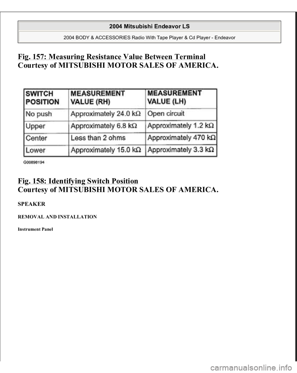
Fig. 157: Measuring Resistance Value Between Terminal
Courtesy of MITSUBISHI MOTOR SALES OF AMERICA.
Fig. 158: Identifying Switch Position
Courtesy of MITSUBISHI MOTOR SALES OF AMERICA.
SPEAKER REMOVAL AND INSTALLATION Instrument Panel
2004 Mitsubishi Endeavor LS
2004 BODY & ACCESSORIES Radio With Tape Player & Cd Player - Endeavor
Page 2380 of 3870
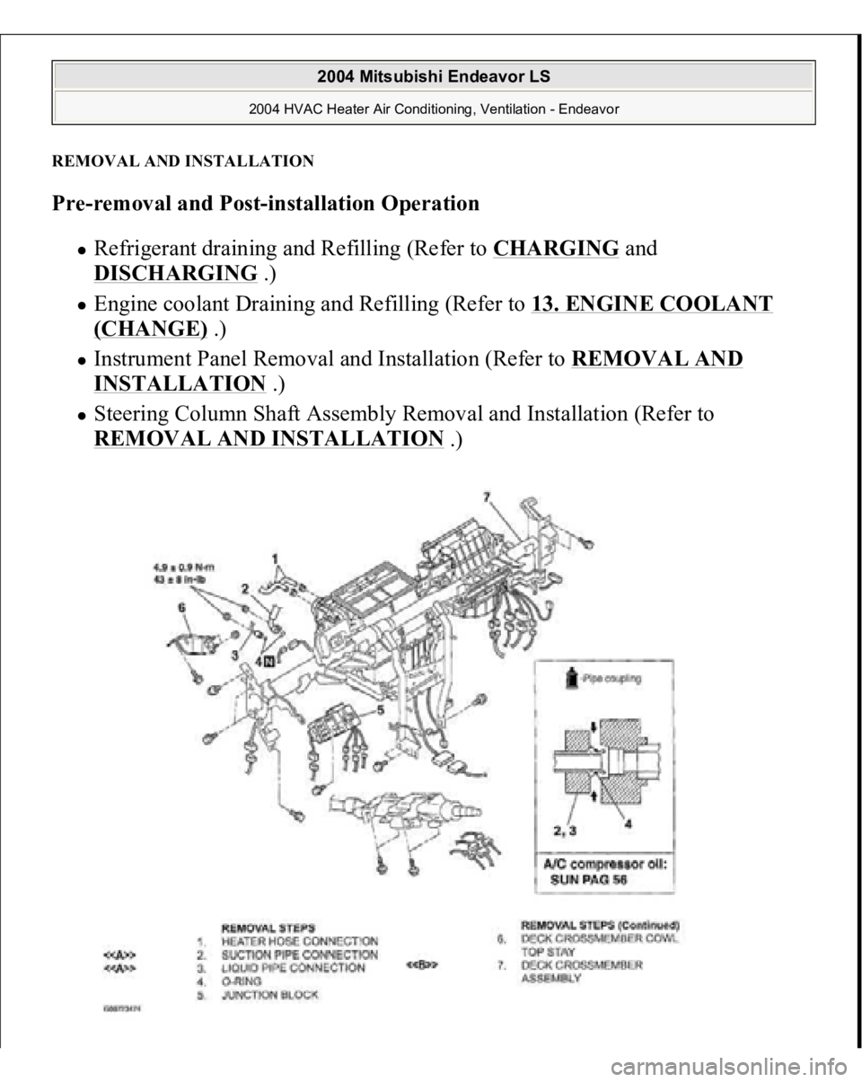
REMOVAL AND INSTALLATIONPre-removal and Post-installation Operation
Refrigerant draining and Refilling (Refer to
CHARGING
and
DISCHARGING
.)
Engine coolant Draining and Refilling (Refer to
13. ENGINE COOLANT
(CHANGE)
.)
Instrument Panel Removal and Installation (Refer to
REMOVAL AND
INSTALLATION
.)
Steering Column Shaft Assembly Removal and Installation (Refer to REMOVAL AND INSTALLATION
.)
2004 Mitsubishi Endeavor LS
2004 HVAC Heater Air Conditioning, Ventilation - Endeavor