Page 706 of 3870

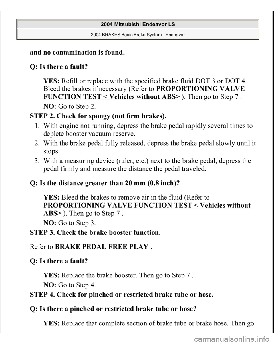
and no contamination is found
.
Q: Is there a fault?
YES: Refill or replace with the specified brake fluid DOT 3 or DOT 4.
Bleed the brakes if necessary (Refer to PROPORTIONING VALVE
FUNCTION TEST < Vehicles without ABS>
). Then go to Step 7 .
NO: Go to Step 2.
STEP 2. Check for spongy (not firm brakes).
1. With engine not running, depress the brake pedal rapidly several times to
deplete booster vacuum reserve.
2. With the brake pedal fully released, depress the brake pedal slowly until it
stops.
3. With a measuring device (ruler, etc.) next to the brake pedal, depress the
pedal firmly and measure the distance the pedal traveled.
Q: Is the distance greater than 20 mm (0.8 inch)?
YES: Bleed the brakes to remove air in the fluid (Refer to
PROPORTIONING VALVE FUNCTION TEST < Vehicles without
ABS>
). Then go to Step 7 .
NO: Go to Step 3.
STEP 3. Check the brake booster function.
Refer to BRAKE PEDAL FREE PLAY
.
Q: Is there a fault?
YES: Replace the brake booster. Then go to Step 7 .
NO: Go to Step 4.
STEP 4. Check for pinched or restricted brake tube or hose.
Q: Is there a pinched or restricted brake tube or hose?
YES: Replace that complete section of brake tube or brake hose. Then go
2004 Mitsubishi Endeavor LS
2004 BRAKES Basic Brake System - Endeavor
Page 707 of 3870

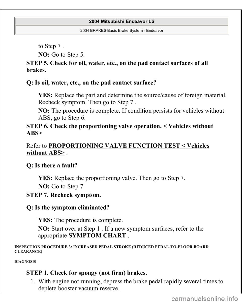
to Step 7 .
NO: Go to Step 5.
STEP 5. Check for oil, water, etc., on the pad contact surfaces of all
brakes.
Q: Is oil, water, etc., on the pad contact surface?
YES: Replace the part and determine the source/cause of foreign material.
Recheck symptom. Then go to Step 7 .
NO: The procedure is complete. If condition persists for vehicles without
ABS, go to Step 6.
STEP 6. Check the proportioning valve operation. < Vehicles without
ABS>
Refer to PROPORTIONING VALVE FUNCTION TEST < Vehicles
without ABS>
.
Q: Is there a fault?
YES: Replace the proportioning valve. Then go to Step 7.
NO: Go to Step 7.
STEP 7. Recheck symptom.
Q: Is the symptom eliminated?
YES: The procedure is complete.
NO: Start over at Step 1 . If a new symptom surfaces, refer to the
appropriate SYMPTOM CHART
.
INSPECTION PROCEDURE 3: INCREASED PEDAL STROKE (REDUCED PEDAL-TO-FLOOR BOARD
CLEARANCE) DIAGNOSIS
STEP 1. Check for spongy (not firm) brakes.
1. With engine not running, depress the brake pedal rapidly several times to
de
plete booster vacuum reserve.
2004 Mitsubishi Endeavor LS
2004 BRAKES Basic Brake System - Endeavor
Page 732 of 3870
2. If the brake pedal play is not within the standard value, check the following,
and adjust or replace if necessary:
Excessive play between the brake pedal and the clevis pin, or between the
clevis pin and the brake booster operating rod Brake pedal height Installation position of the stop light switch, etc.
CLEARANCE BETWEEN BRAKE PEDAL AND DASH PANEL 1. Turn up the carpet, etc. under the brake pedal.
2. Start the engine, depress the brake pedal with approximately 500 N (112
pounds) of force, and measure the clearance between the brake pedal and the
dash panel.
Standard value: 110 mm (4.33 inches) or more [From the surface of dash
panel to the face of
pedal
pad]
2004 Mitsubishi Endeavor LS
2004 BRAKES Basic Brake System - Endeavor
Page 734 of 3870
3. If the clearance is outside the standard value, check for air trapped in the brake
line and thickness of the disc brake pad. And then adjust and replace defective
parts as required.
4. Return the carpet etc. to its original position. BRAKE BOOSTER OPERATING TEST 1. For simple checking of the brake booster operation, carry out the following
tests:
1. Run the engine for one or two minutes, and then stop it. If the pedal
depresses fully the first time but gradually becomes higher when
depressed succeeding times, the booster is operating properly. If the pedal
height remains unchanged, the booster is defective. Go to step 2.
Fig. 19: Checking Brake Booster Operation
Courtesy of MITSUBISHI MOTOR SALES OF AMERICA.
2004 Mitsubishi Endeavor LS
2004 BRAKES Basic Brake System - Endeavor
Page 735 of 3870
2. With the engine stopped, step on the brake pedal several times. Then step
on the brake pedal and start the engine. If the pedal moves downward
slightly, the booster is in good condition. If there is no change, the booster
is defective. Go to step 3.
Fig. 20: Stepping On Pedal & Starting Engine
Courtesy of MITSUBISHI MOTOR SALES OF AMERICA.
3. With the engine running, step on the brake pedal and then stop the engine.
Hold the pedal depressed for 30 seconds. If the pedal height does not
change, the booster is in good condition, if the pedal rises, the booster is
defective.
2004 Mitsubishi Endeavor LS
2004 BRAKES Basic Brake System - Endeavor
Page 736 of 3870
Fig. 21: Stepping On Pedal & Stopping Engine
Courtesy of MITSUBISHI MOTOR SALES OF AMERICA.
2. If the above three tests are okay, the booster is OK. If one of the above three
tests is not okay, the check valve, vacuum hose, or booster is defective. Check
the check valve (Refer to CHECK VALVE OPERATION CHECK
),
vacuum hose for leaks, high volume engine vacuum applied to booster. Repair
or replace as necessary. If these are OK, replace booster and repeat this test
starting at Step 1.
CHECK VALVE OPERATION CHECK 1. Remove the vacuum hose. (Refer to MASTER CYLINDER ASSEMBLY
AND BRAKE BOOSTE
R).
CAUTION: The check valve should not be removed from the
vacuum hose.
2004 Mitsubishi Endeavor LS
2004 BRAKES Basic Brake System - Endeavor
Page 776 of 3870
1. Start the engine and hold the brake pedal down for 5 seconds. [Pedal
depression force: approximately 200 N (45 pound)]
2. Stop the engine.
3. Turn the brake disc forward 10 times.
4. Use a spring scale to measure the hub torque with pads installed in the
same direction as earlier.
5. Calculate the drag force of the disc brake [difference between hub torque
with pads installed and hub torque with pads removed].
Standard value: 68 N (15 pounds) or less
Fig. 54: Measuring Drag Force
Courtes
y of MITSUBISHI MOTOR SALES OF AMERICA
.
2004 Mitsubishi Endeavor LS
2004 BRAKES Basic Brake System - Endeavor
Page 792 of 3870

2004 ENGINE COOLING
Electric Cooling Fans - Endeavor
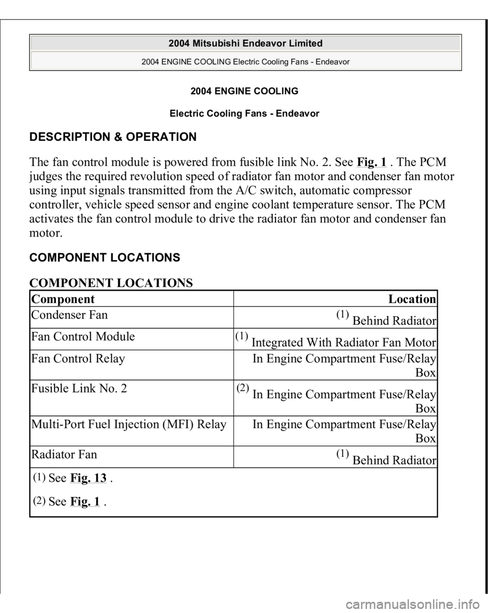
DESCRIPTION & OPERATION The fan control module is powered from fusible link No. 2. See Fig. 1
. The PCM
judges the required revolution speed of radiator fan motor and condenser fan motor
using input signals transmitted from the A/C switch, automatic compressor
controller, vehicle speed sensor and engine coolant temperature sensor. The PCM
activates the fan control module to drive the radiator fan motor and condenser fan
motor. COMPONENT LOCATIONS COMPONENT LOCATIONS Component
Location
Condenser Fan
(1) Behind Radiator
Fan Control Module
(1) Integrated With Radiator Fan Motor
Fan Control Relay
In Engine Compartment Fuse/Relay
Box
Fusible Link No. 2
(2) In Engine Compartment Fuse/Relay
Box
Multi-Port Fuel Injection (MFI) Relay
In Engine Compartment Fuse/Relay
Box
Radiator Fan
(1) Behind Radiator
(1)
See Fig. 13
.
(2)
See Fig. 1
.
2004 Mitsubishi Endeavor Limited
2004 ENGINE COOLING Electric Cooling Fans - Endeavor
2004 Mitsubishi Endeavor Limited
2004 ENGINE COOLING Electric Cooling Fans - Endeavor