Page 983 of 3870
pressed. If the values measured at the time correspond to those in the table below, the resistance values are correct.
2004 Mitsubishi Endeavor LS
2004 BODY & ACCESSORIES Auto, Cruise Control System - Endeavor
Page 1068 of 3870
2 .
3. Turn the ignition switch to the ON position and select BELT TENSION
MEASUREMENT from the menu screen on Scan Tool (MB991958).
4. Hold Microphone (part of Belt Drive Meter Set) (MB991668) near the center
of the drive belt between the pulleys away from the rear surface of the belt and
perpendicular to the belt (no more then 15 degrees in either direction). See Fi
g.
3 and Fig. 4
.
5. Gently tap the middle of the belt between the pulleys with your finger, and
check that the vibration frequency of the belt is within specification. See Fig. 3
and Fig. 4
. See DRIVE BELT ADJUSTMENT SPECIFICATIONS
table.
CAUTION: Temperature of the surface of the belt should be
as close possible to underhood temperature.
CAUTION: DO NOT let contaminants such as water or oil get
onto the microphone. If strong gusts of wind
blow against the microphone or if there are any
loud sources of noise nearby, the values
measured by the microphone may not
correspond to actual values. DO NOT take
measurement while engine is running.
2004 Mitsubishi Endeavor Limited
2004 ENGINE COOLING Specifications & Drive Belt Routing - Endeavor
Page 1097 of 3870
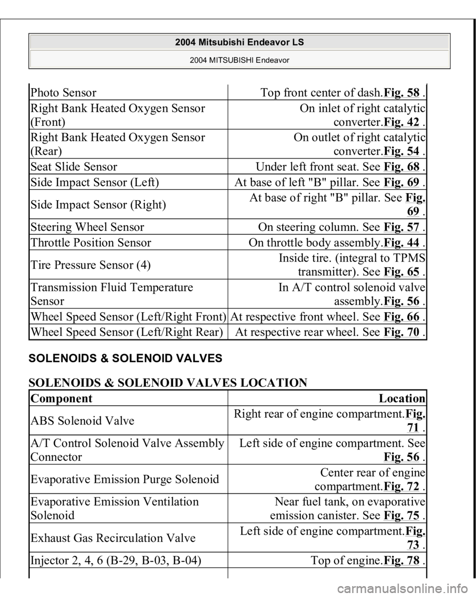
SOLENOIDS & SOLENOID VALVES SOLENOIDS & SOLENOID VALVES LOCATION Photo Sensor
Top front center of dash.Fig. 58
.
Right Bank Heated Oxygen Sensor
(Front)
On inlet of right catalytic
converter.Fig. 42
.
Right Bank Heated Oxygen Sensor
(Rear)
On outlet of right catalytic
converter.Fig. 54
.
Seat Slide Sensor
Under left front seat. See Fig. 68
.
Side Impact Sensor (Left)
At base of left "B" pillar. See Fig. 69
.
Side Impact Sensor (Right)
At base of right "B" pillar. See Fig.
69 .
Steering Wheel Sensor
On steering column. See Fig. 57
.
Throttle Position Sensor
On throttle body assembly.Fig. 44
.
Tire Pressure Sensor (4)
Inside tire. (integral to TPMS
transmitter). See Fig. 65
.
Transmission Fluid Temperature
Sensor
In A/T control solenoid valve
assembly.Fig. 56
.
Wheel Speed Sensor (Left/Right Front)
At respective front wheel. See Fig. 66
.
Wheel Speed Sensor (Left/Right Rear)
At respective rear wheel. See Fig. 70
.
Component
Location
ABS Solenoid Valve
Right rear of engine compartment.Fig.
71 .
A/T Control Solenoid Valve Assembly
Connector
Left side of engine compartment. See
Fig. 56
.
Evaporative Emission Purge Solenoid
Center rear of engine
compartment.Fig. 72
.
Evaporative Emission Ventilation
Solenoid
Near fuel tank, on evaporative
emission canister. See Fig. 75
.
Exhaust Gas Recirculation Valve
Left side of engine compartment.Fig.
73 .
Injector 2, 4, 6 (B-29, B-03, B-04)
Top of engine.Fig. 78
.
2004 Mitsubishi Endeavor LS
2004 MITSUBISHI Endeavor
Page 1302 of 3870
cleaned regularly and kept separate from personal clothing. Where there is a risk of eye contact, eye protection should be worn i.e.
chemical goggles or face shields. In addition, an eye wash facility should be
provided. Obtain First Aid treatment immediately for open cuts and wounds. Wash regularly with soap and water to ensure all oil is removed, especially
before meals (skin cleansers and nail brushes will help). After cleaning, apply
lotion, etc., containing lanolin to replace natural skin oils is advised. Do not use gasoline, kerosene, diesel fuel, gas oil, thinner or solvents for
cleaning skin. Apply barrier creams before each work period to help clean the skin after
work. If skin disorders develop, obtain medical advice immediately.
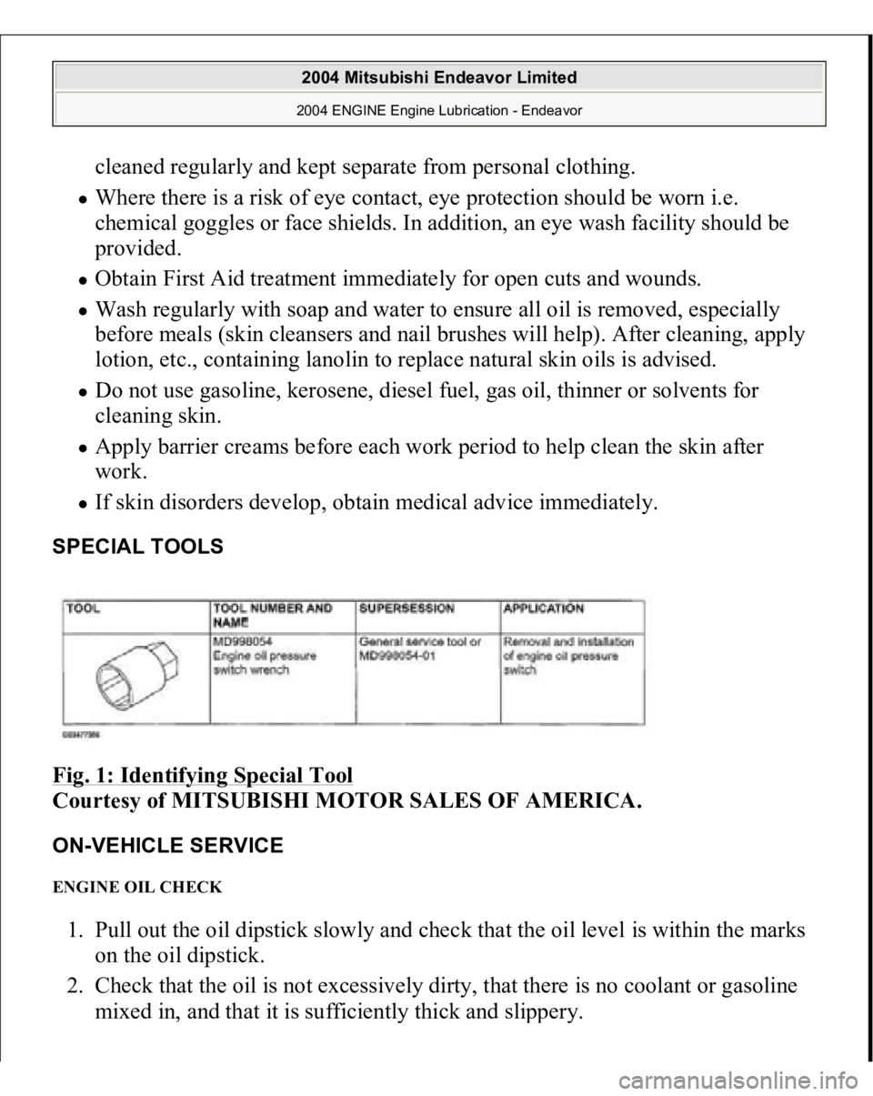
SPECIAL TOOLS Fig. 1: Identifying Special Tool
Courtesy of MITSUBISHI MOTOR SALES OF AMERICA.
ON-VEHICLE SERVICE ENGINE OIL CHECK 1. Pull out the oil dipstick slowly and check that the oil level is within the marks
on the oil dipstick.
2. Check that the oil is not excessively dirty, that there is no coolant or gasoline
mixed in, and that it is sufficientl
y thick and sli
ppery.
2004 Mitsubishi Endeavor Limited 2004 ENGINE Engine Lubrication - Endeavor
Page 1461 of 3870
Fig. 134: Installing Connecting Rod Cap Nu
t
Courtesy of MITSUBISHI MOTOR SALES OF AMERICA.
INSPECTION PISTON Replace the piston if scratches or seizure is evident on its surfaces (especially the
thrust surface). Replace the piston if it is cracked. PISTON PIN 1. Insert the piston pin into the piston pin hole with a thumb. You should feel a
slight resistance. Replace the piston pin if it can be easily inserted or there is
excessive play.
2. The piston and piston pin must be replaced as an assembly. PISTON RING 1. Check the piston ring for damage, excessive wear, and breakage. Replace if
defects are evident. If the piston has been replaced with a new one, the piston
rings must also be replaced with new ones.
2. Check for clearance between the piston ring and ring groove. If the limit is
exceeded, replace the ring or piston, or both.
Standard Value:
Number 1: 0.03 - 0.07 mm (0.0012 - 0.0027 inch)
Number 2: 0.02 - 0.06 mm (0.0008 - 0.0023 inch)
Limit: 0.1 mm (0.003 inch)
2004 Mitsubishi Endeavor Limited 2004 ENGINE Engine Overhaul - Endeavor
Page 1501 of 3870
Courtesy of MITSUBISHI MOTOR SALES OF AMERICA
.
2. Connect scan tool MB991958 to the data link connector.
3. Turn the ignition switch to the "ON" and select scan tool MB991958 "Belt
Tension Measurement" from the menu screen.
4. Hold special tool MB991668 (microphone) to the middle of the drive belt
between the pulleys (at the place indicated by the arrow), about 10 - 20 mm
(0.4 - 0.8 inch) away from the rear surface of the belt and so that it is
perpendicular to the belt (within an angle of +/-15 degree angle).
5. Gently tap the middle of the belt between the pulleys (the place indicated by
the arrow) with your finger as shown in the illustration, and check that the
vibration fre
quenc
y of the belt is within the stan
dard value.
CAUTION:
The temperature of the surface of the belt
should be as close as possible to underhood
temperature. Do not let an
y contaminants such as water or
oil get onto the microphone.
If strong gusts of wind blow against the
microphone or if there are any loud sources
of noise nearby, the values measured by the
microphone may not correspond to actual
values. If the microphone is touching the belt while
the measurement is being made, the values
measured by the microphone may not
correspond to actual values. Do not take the measurement while the
vehicle's engine is running.
2004 Mitsubishi Endeavor Limited
2004 ENGINE Engine - Endeavor
Page 1511 of 3870
Fig. 13: Connecting Special Tool MB991668 To Scan Tool MB99195
Courtesy of MITSUBISHI MOTOR SALES OF AMERICA.
2. Connect scan tool MB991958 to the data link connector.
3. Turn the ignition switch to the "ON" position and select "Belt Tension
Measurement" from the special tool MB991824 screen menu.
4. Hold special tool MB991668 (microphone) to the middle of the drive belt
between the pulleys (at the place indicated by the arrow), about 10 - 20 mm
(0.4 - 0.8 inch) away from the rear surface of the belt and so that it is
perpendicular to the belt (within an angle of+/-15 degree angle).
5. Gently tap the middle of the belt between the pulleys (the place indicated by
the arrow) with your finger as shown in the illustration, and check that the
vibration frequency of the belt is within the stan
dard value.
CAUTION:
The temperature of the surface of the belt
should be as close as possible to underhood
temperature. Do not let any contaminants such as water or
oil get onto the microphone. If strong gusts of wind blow against the
microphone or if there are any loud sources
of noise nearby, the values measured by the
microphone may not correspond to actual
values. If the microphone is touching the belt while
the measurement is being made, the values
measured by the microphone may not
correspond to actual values. Do not take the measurement while the
vehicle's engine is running.
2004 Mitsubishi Endeavor Limited
2004 ENGINE Engine - Endeavor
Page 1531 of 3870
the vacuum gauge reading.
Idle speed: 680+/-100 r/min
Minimum limit: 60 kPa (18 in Hg)
LASH ADJUSTER CHECK If an abnormal noise (chattering noise) suspected to be caused by malfunction of the
lash adjuster is produced immediately after starting the engine and does not
disappear, perform the following check.
1. Start the engine.
2. Check if the abnormal noise produced immediately after starting the engine,
changes with the change in the engine speed.
If the abnormal noise is not produced immediately after starting the engine or it
does not change with the engine speed, the lash adjuster is not the cause for the
noise.
Therefore, investigate other causes. The abnormal noise is probably caused by
some other parts than the engine proper if it does not change with the engine
speed. (In this case, the lash adjuster is in good condition.)NOTE: An abnormal noise due to malfunction of the lash adjuster
is produced immediately after starting the engine and
changes with the engine speed, irrespective of the engine
load. If, the abnormal noise is not produced immediately
after starting the engine or does not change with the engine
speed, or it changes with the engine load, the lash adjuster
is not the cause for the abnormal noise.
NOTE: When the lash adjuster is malfunctioning, the abnormal
noise is rarely eliminated by continuing the warming-up of
the engine at idle speed.
However, the abnormal noise may disappear only when
seizure is caused by oil sludge in the engine whose oil is
not maintained properly.
2004 Mitsubishi Endeavor Limited
2004 ENGINE Engine - Endeavor