2004 MITSUBISHI ENDEAVOR table
[x] Cancel search: tablePage 238 of 3870
YES: Check the brake system related components except the ABS system.
NO: The procedure is complete.
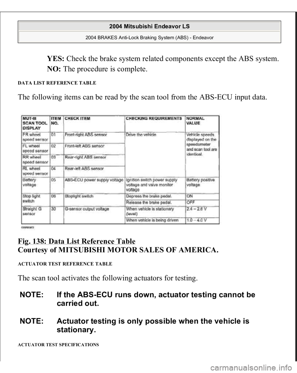
DATA LIST REFERENCE TABLE The following items can be read by the scan tool from the ABS-ECU input data.
Fig. 138: Data List Reference Table
Courtesy of MITSUBISHI MOTOR SALES OF AMERICA.
ACTUATOR TEST REFERENCE TABLE The scan tool activates the following actuators for testing. ACTUATOR TEST SPECIFICATIONS NOTE: If the ABS-ECU runs down, actuator testing cannot be
carried out.
NOTE: Actuator testing is only possible when the vehicle is
stationary.
2004 Mitsubishi Endeavor LS
2004 BRAKES Anti-Lock Braking System (ABS) - Endeavor
Page 243 of 3870
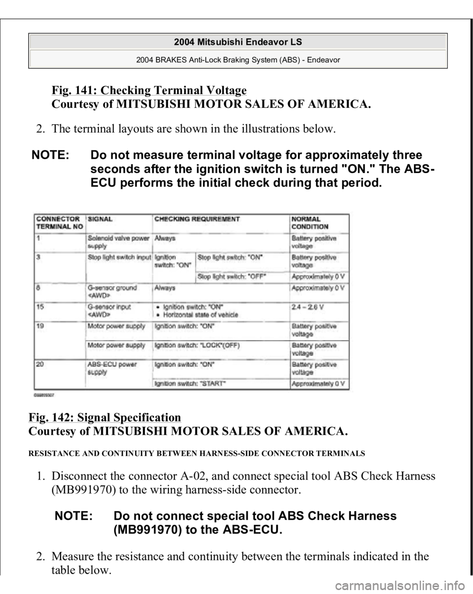
Fig. 141: Checking Terminal Voltage
Courtesy of MITSUBISHI MOTOR SALES OF AMERICA.
2. The terminal layouts are shown in the illustrations below.
Fig. 142: Signal Specification
Courtesy of MITSUBISHI MOTOR SALES OF AMERICA.
RESISTANCE AND CONTINUITY BETWEEN HARNESS-SIDE CONNECTOR TERMINALS 1. Disconnect the connector A-02, and connect special tool ABS Check Harness
(MB991970) to the wiring harness-side connector.
2. Measure the resistance and continuity between the terminals indicated in the
table below. NOTE: Do not measure terminal voltage for approximately three
seconds after the ignition switch is turned "ON." The ABS-
ECU performs the initial check during that period.
NOTE: Do not connect special tool ABS Check Harness
(MB991970) to the ABS-ECU.
2004 Mitsubishi Endeavor LS
2004 BRAKES Anti-Lock Braking System (ABS) - Endeavor
Page 256 of 3870
actuator is force-driven. The result should be as shown in the diagram above.
HYDRAULIC UNIT CHECK
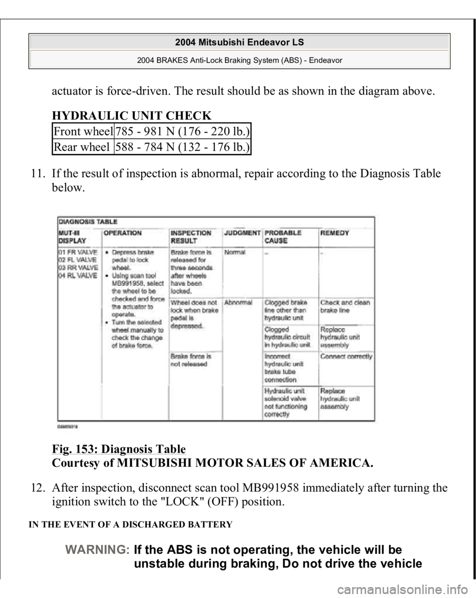
11. If the result of inspection is abnormal, repair according to the Diagnosis Table
below.
Fig. 153: Diagnosis Table
Courtesy of MITSUBISHI MOTOR SALES OF AMERICA.
12. After inspection, disconnect scan tool MB991958 immediately after turning the
ignition switch to the "LOCK" (OFF) position.
IN THE EVENT OF A DISCHARGED BATTERY
Front wheel
785 - 981 N (176 - 220 lb.)
Rear wheel
588 - 784 N (132 - 176 lb.)
WARNING:If the ABS is not operating, the vehicle will be
unstable during braking, Do not drive the vehicle
2004 Mitsubishi Endeavor LS
2004 BRAKES Anti-Lock Braking System (ABS) - Endeavor
Page 281 of 3870
When a vehicle has been involved in a collision, certain components of the passive
restraint system must be inspected or replaced. See
AIR BAG/SRS
COMPONENT INSPECTION & REPLACEMENT TABLES
article in the
GENERAL INFORMATION section.
REMOVAL & INSTALLATION DRIVER-SIDE AIR BAG MODULE & CLOCKSPRING Removal & Installation (With Single-stage AIR Bag System) 1. Before proceeding, see
AIR BAG SAFETY PRECAUTIONS
. Ensure front
wheels are in straight-ahead position. Turn ignition off. Disable air bag system.
See
DISABLING & ACTIVATING AIR BAG SYSTEM
.
2. Remove lower cover from steering wheel. Remove driver-side air bag module
bolts from rear of steering wheel. Remove driver-side air bag module. See
Fig.
3 . Remove damper weight from steering wheel. Remove steering wheel nut
and discard. Using Steering Wheel Puller (MB990803), remove steering wheel.
3. Remove upper and lower steering column covers. Disconnect clockspring
electrical connectors. Remove clockspring screws. Remove clockspring from
steering column.
4. To install, reverse removal procedure. If necessary, center clockspring. See CENTERING CLOCKSPRING
under ADJUSTMENTS. Tighten
clockspring screws, NEW steering wheel nut and driver-side air bag module
bolts to specification. See
TORQUE SPECIFICATIONS
. Activate air bag
s
ystem. WARNING:Accidental air bag deployment is possible. Personal
injury may result. Read and follow all WARNINGS
and AIR BAG SAFETY PRECAUTIONS
before
working on air bag system or related components.
2004 Mitsubishi Endeavor Limited
2004 ACCESSORIES/SAFETY EQUIPMENT Mitsubishi - Air Bag Restraint Systems
Page 300 of 3870
1. Turn ignition on. If AIR BAG warning light comes on for 7 seconds and then
goes off, SRS is functioning properly. If AIR BAG warning light does not
function as described, turn ignition off. If AIR BAG warning light malfunction
or scan tool communication problems are encountered, diagnose malfunction
using appropriate table. SeeSCAN TOOL COMMUNICATION
SYMPTOMS (SINGLE
-STAGE AIR BAG SYSTEMS)
and SCAN TOOL
COMMUNICATION SYMPTOMS (DUAL
-STAGE AIR BAG
SYSTEMS)
tables.
2. Utilizing a laptop computer, check for Diagnostic Trouble Codes (DTCs) by
connecting Scan Tool (MB991958) to Data Link Connector (DLC), located
under left side of instrument panel, using Vehicle Communication Interface
(MB991824), USB Cable (MB991827) and Main Harness (MB991911). See
Fig. 18
. Turn ignition on and follow instructions provided with scan tool.
Diagnose displayed DTCs for appropriate air bag system. See SCAN TOOL
COMMUNICATION SYMPTOMS (SINGLE
-STAGE AIR BAG
SYSTEMS)
and SCAN TOOL COMMUNICATION SYMPTOMS
(DUAL
-STAGE AIR BAG SYSTEMS)
. When diagnosis and repairs are
com
plete, erase DTCs.
2004 Mitsubishi Endeavor Limited
2004 ACCESSORIES/SAFETY EQUIPMENT Mitsubishi - Air Bag Restraint Systems
Page 403 of 3870
step.
2. Erase, then retrieve DTCs. Turn ignition off. If DTCs are retrieved, go to next
step. If DTCs are not retrieved, an intermittent condition may exist.
3. If DTC B1530, B1531, B1532, B1533, B1534, B1535, B1536, B1537, B1538,
B1539, B1540, B1541, B1542, B1543, B1545 or B1546 is retrieved, diagnose
appropriate DTC. See DIAGNOSTIC TROUBLE CODES (DTCS) IDENTIFICATION WITH SINGLE
-STAGE AIR BAG SYSTEM
table. If
DTC B1530, B1531, B1532, B1533, B1534, B1535, B1536, B1537, B1538,
B1539, B1540, B1541, B1542, B1543, B1545 or B1546 is not retrieved, go to
next step.
4. Visually inspect passenger seat belt warning light connector C-38. See Fig. 30
.
If connector C-38 is connected correctly, go to next step. If connector C-38 is
not connected correctly, properly connect connector. Go to step 10 .
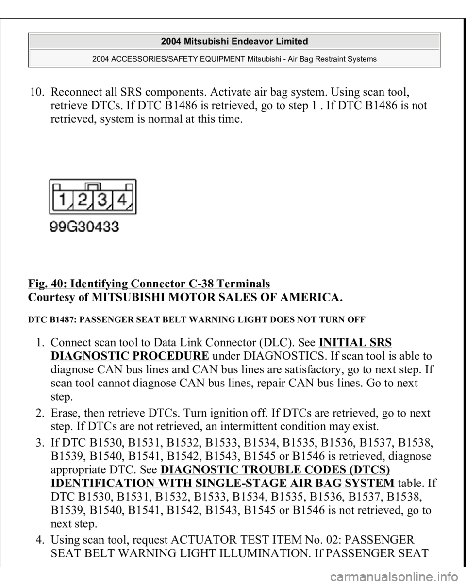
5. Disconnect connector C-38. Measure voltage between ground and connector
C-38, terminal No. 1 (Black/White wire). See Fig. 40
. If voltage is not about
12 volts, go to next step. If voltage is about 12 volts, go to step 7 .
6. Inspect Black/White wire between terminal No. 1 of connector C-38 and
terminal No. 2 of ignition switch connector C-308, including junction block
connectors C-211 and C-215. See Fig. 22
. If wire is okay, go to next step. If
wire is not okay, repair as necessary. See WIRE REPAIR
. Go to step 10 .
7. Inspect SRS ECU connector C-26. See SRS ELECTRONIC CONTROL
UNIT (SRS ECU)
under REMOVAL & INSTALLATION. If SRS ECU
connector C-26 is connected correctly, go to next step. If SRS ECU connector
C-26 is not connected correctly, properly connect connector. Go to step 10 .
8. Check Pink wire between connector C-07, terminal No. 3 and SRS ECU
connector C-26, terminal No. 42, for damage, shorts or open circuits. See Fig.
33 . If wire is okay, go to next step. If wire is not okay, repair as necessary. See
WIRE REPAIR
. Go to step 10 .
9. Disconnect negative battery cable. Disconnect SRS ECU connector C-26.
Connect negative battery cable. Connect a jumper wire between ground and
SRS ECU connector C-26, terminal No. 42. If passenger seat belt warning light
does not illuminate, replace passenger seat belt warning light assembly. Go to
next step. If passenger seat belt warning light illuminates, erase, then retrieve
DTCs. If DTC B1487 is retrieved, re
place SRS ECU. Go to next ste
p.
2004 Mitsubishi Endeavor Limited
2004 ACCESSORIES/SAFETY EQUIPMENT Mitsubishi - Air Bag Restraint Systems
Page 404 of 3870
10. Reconnect all SRS components. Activate air bag system. Using scan tool,
retrieve DTCs. If DTC B1486 is retrieved, go to step 1 . If DTC B1486 is not
retrieved, system is normal at this time.
Fig. 40: Identifying Connector C
-38 Terminals
Courtesy of MITSUBISHI MOTOR SALES OF AMERICA.
DTC B1487: PASSENGER SEAT BELT WARNING LIGHT DOES NOT TURN OFF 1. Connect scan tool to Data Link Connector (DLC). See INITIAL SRS
DIAGNOSTIC PROCEDURE
under DIAGNOSTICS. If scan tool is able to
diagnose CAN bus lines and CAN bus lines are satisfactory, go to next step. If
scan tool cannot diagnose CAN bus lines, repair CAN bus lines. Go to next
step.
2. Erase, then retrieve DTCs. Turn ignition off. If DTCs are retrieved, go to next
step. If DTCs are not retrieved, an intermittent condition may exist.
3. If DTC B1530, B1531, B1532, B1533, B1534, B1535, B1536, B1537, B1538,
B1539, B1540, B1541, B1542, B1543, B1545 or B1546 is retrieved, diagnose
appropriate DTC. See DIAGNOSTIC TROUBLE CODES (DTCS)
IDENTIFICATION WITH SINGLE
-STAGE AIR BAG SYSTEM
table. If
DTC B1530, B1531, B1532, B1533, B1534, B1535, B1536, B1537, B1538,
B1539, B1540, B1541, B1542, B1543, B1545 or B1546 is not retrieved, go to
next step.
4. Using scan tool, request ACTUATOR TEST ITEM No. 02: PASSENGER
SEAT BELT WARNING LIGHT ILLUMINATION. If PASSENGER SEAT
2004 Mitsubishi Endeavor Limited
2004 ACCESSORIES/SAFETY EQUIPMENT Mitsubishi - Air Bag Restraint Systems
Page 406 of 3870
appropriate DTC. See DIAGNOSTIC TROUBLE CODES (DTCS) IDENTIFICATION WITH SINGLE
-STAGE AIR BAG SYSTEM
table. If
DTC B1540, B1541, B1542, B1543, B1545 or B1546 is not retrieved, go to
next step.
4. Visually inspect PASSENGER AIR BAG OFF indicator connector C-37. See
Fig. 30
. If connector C-37 is connected correctly, go to next step. If connector
C-37 is not connected correctly, properly connect connector. Go to step 10 .
5. Disconnect connector C-37. Measure voltage between ground and connector
C-37, terminal No. 1 (Black/White wire). See Fig. 41
. If voltage is not about
12 volts, go to next step. If voltage is about 12 volts, go to step 7 .
6. Inspect Black/White wire between terminal No. 1 of connector C-37 and
terminal No. 2 of ignition switch connector C-308, including junction block
connectors C-211 and C-215. See Fig. 22
. If wire is okay, go to next step. If
wire is not okay, repair as necessary. See WIRE REPAIR
. Go to step 10 .
7. Inspect SRS ECU connector C-26. See SRS ELECTRONIC CONTROL
UNIT (SRS ECU)
under REMOVAL & INSTALLATION. If SRS ECU
connector C-26 is connected correctly, go to next step. If SRS ECU connector
C-26 is not connected correctly, properly connect connector. Go to step 10 .
8. Check Blue/Yellow wire between connector C-37, terminal No. 3 and SRS
ECU connector C-26, terminal No. 21, for damage, shorts or open circuits. See
Fig. 33
. If wire is okay, go to next step. If wire is not okay, repair as
necessary. Go to step 10 .
9. Disconnect negative battery cable. Disconnect SRS ECU connector C-26.
Connect negative battery cable. Connect a jumper wire between ground and
SRS ECU connector C-26, terminal No. 21. If PASSENGER AIR BAG OFF
warning light does not illuminate, replace PASSENGER AIR BAG OFF
warning light assembly. Go to next step. If PASSENGER AIR BAG OFF
warning light illuminates, erase, then retrieve DTCs. If DTC B1489 is
retrieved, replace SRS ECU. Go to next step.
10. Reconnect all SRS components. Activate air bag system. Using scan tool,
retrieve DTCs. If DTC B1489 is retrieved, go to step 1 . If DTC B1489 is not
retrieved, s
ystem is normal at this time.
2004 Mitsubishi Endeavor Limited
2004 ACCESSORIES/SAFETY EQUIPMENT Mitsubishi - Air Bag Restraint Systems