Page 65 of 152

63
OVERVIEW REPAIRS OPERATIONCONTROLS DATA INDEX
FLAT TIRE MONITORFlat tireIndicator lamp:
The indicator lamp in the display
elements flashes. In addition, an
acoustic signal sounds.
1. Reduce speed and stop the vehicle with
caution. Avoid hard brake applications
and steering maneuvers
2. Determine which tire is damaged
If this cannot be determined, con-
tact your MINI Dealer.<
3. Replace the damaged tire, refer to
Changing tires on page 117, or repair the
flat tire using the MINI Moblity System,
refer to page 121.
Vehicles with Run Flat tires:
1. Reduce vehicle speed carefully to under
50 mph / 80 km/h. Avoid hard brake
applications and steering maneuvers.
Do not exceed a speed of 50 mph /
80 km/h
Since Run Flat tires are reinforced
on the flanks, it is usually not pos-
sible to detect a loss of pressure from
the outside, refer to Run Flat tires on
page 93.<
2. To continue driving, follow the instruc-
tions on driving with damaged tires on
page 93.System malfunctionIndicator lamp:
The symbol in the instrument clus-
ter lights up. The Flat Tire Monitor
is malfunctioning or out of order.
Please contact your MINI Dealer.
Page 66 of 152

*
The concept
The PDC assists you when you back into a
parking space. A signal tone tells you the
current distance to an object behind your
vehicle. To do this, four")
64
PARK DISTANCE CONTROL (PDC)
*
The concept
The PDC assists you when you back into a
parking space. A signal tone tells you the
current distance to an object behind your
vehicle. To do this, four ultrasonic sensors
in the rear bumper measure the distance to
the nearest object.
The sensors on each side have a range of
approx. 2 ft / 60 cm, the middle sensors
one of approx. 5 ft / 1.5 m.
PDC is a parking aid that can identify
objects if they are approached slowly,
as is generally the case when parking.
Avoid driving towards objects rapidly; due
to underlying physical principles, the sys-
tem may otherwise alert you too late for
you to take evasive steps.
tem starts to operate automatically about
one second after you select reverse gear or
place the selector lever in position R.
Wait for this one second before you
drive backwards.<
The system is deactivated when you shift
away from Reverse.
You can have a signal tone set by your
MINI Dealer as a confirmation that
PDC has been activated.<
Acoustical signalsThe distance to an object is indicated by a
tone sounding at intervals. As the distance
between vehicle and object decreases, the
intervals between the tones become
shorter. A continuous tone indicates the
presence of an object less than 8 in / 20 cm
away.
The warning signal is canceled after
approx. three seconds if the distance to the
object remains constant during this time,
for instance if you are moving parallel to a
wall.MalfunctionSystem malfunctions will be indicated by a
continuous high-pitched tone when the
system is activated the first time. Please
have your MINI Dealer resolve the problem.Volume controlThe volume of the Park Distance Control
signal can be adjusted from level 1, soft, to
level 6, loud.
The volume can be set by your MINI
Dealer.<
System limitations
Even with PDC, final responsibility for
estimating the distance between the
vehicle and any objects always remains
with the driver.
Even when sensors are involved, there is a
blind spot in which objects cannot be de-
tected. Recognition of some objects can be
beyond the limits of physical ultrasonic
measurement, for example with towing
bars or hitches or with thin or wedge-
shaped objects. Moreover, low objects that
have already been detected, such as a curb
edge, can disappear out of the range of the
sensors before a continuous tone sounds.
Loud sources of sound outside and inside
your vehicle can drown the PDC signal
tone.<
Keep the sensors clean and free of ice
or snow in order to ensure that they
will continue to operate effectively.
Do not apply high pressure spray to the
sensors for a prolonged period of time.
Always maintain a distance which is
greater than 4 in / 10 cm.<
Page 67 of 152

65
OVERVIEW REPAIRS OPERATIONCONTROLS DATA INDEX
AIRBAGS1Side airbags in seatback on the driver
and passenger side: front
2Head airbags on the driver and passenger
sides for both rows of seats: front/rear
3Front airbags on the driver and passen-
ger sidesProtective effectThe front airbags supplement the safety belts
by providing additional protection for the
driver and front passenger in the event of a
frontal collision in which the protection
afforded by the belts alone may no longer be
sufficient.
When needed, the head and side airbags help
to furnish protection in the event of side
impact.
Each of the side airbags is designed to help
support the seat occupant's upper body.
The airbags are designed to not be trig-
gered in certain types of collisions, e.g. in
minor accidents, certain kinds of vehicle
rollover and rear impact.
For information on the ideal seating position,
refer to page 31.
Do not apply adhesive materials to the
cover panels of the airbags, cover them
or modify them in any other way. Do not fit
covers, cushions or other items to the front
seats that have not been specially approved
for seats with side airbags. Do not hang cloth-
ing, e. g. jackets, over the backrests.
Do not attempt to remove the airbag
restraint system from the vehicle. Do not
make any changes yourself to the individual
components and wiring. This includes the
padded covers of the steering wheel, instru-
ment panel and roof supports, as well as the
sides of the roofliner and the original back-
rest covers on the front seats. Do not attempt
to remove or dismantle the steering wheel.
Do not touch the individual components
directly after the system has been triggered,
as otherwise there is a danger of burns. In the
event of malfunctions, immobilization or use,
i.e. triggering, of the airbag restraint system
in accordance with its intended function,
please commission a MINI Dealer with the
inspection, repair or disassembly. Unprofes-
sional attempts to service the system could
lead to failure in an emergency or undesired
airbag activation, either of which could result
in personal injury. In view of the applicable
safety regulations, please arrange for your
MINI Dealer to dispose of the airbag genera-
tors.<
Airbag warning information is also pro-
vided on the sun visors.Indicator lamp
The indicator lamp in the display
elements shows the status of the
entire airbag system and the seat
belt tensioners starting from ignition key
position 1.
System operational:
>The indicator lamp comes on briefly.
System malfunction:
>The indicator lamp does not come on
starting from ignition key position 1
>The indicator lamp stays lit
>The indicator lamp lights up while driving.
Page 68 of 152
66
AIRBAGS
A system malfunction could prevent
the airbags from deploying in
response to a severe impact occurring
within the system's normal triggering
range. Please have the airbag system
checked as soon as possible by your MINI
Dealer.
<
Page 69 of 152
67
OVERVIEW REPAIRS OPERATIONCONTROLS DATA INDEX
AIR CONDITIONING SYSTEM
*
1Air onto the windshield and onto the
side windows
2Air for the upper body area69
3Air for the front and rear footwells4Temperature68
5Windshield heating68
6Blower for air supply68
7Air conditioning688Air distribution68
9Recirculated air mode68
10 Rear window defroster68
Page 70 of 152

68
AIR CONDITIONING SYSTEM
*
Air supply
You can select blower speeds
from 1 to 4. Position 0: fan is
turned off. The button for recir-
culated air mode fully blocks the
supply of air from outside.
Heating and ventilation operate as of
position 1.
Temperature
Turn to the right, red, to increase
the temperature of the passen-
ger compartment.
Rapid heating: turn to the
extreme right. Then select a pleasant inte-
rior temperature.
Air distribution
Air distribution in upper body
region , upper body region
and footwell , footwell ,
footwell and windows , and
windows .
All intermediate positions are possible,
refer to illustration and overview on
page 67.
Rear window defroster
Rear window defroster switched
on:
Indicator lamp lights up.
As long as the indicator lamp is lit, the
heating operates at high power output:
rapid defrosting.
Indicator lamp goes out.
The heating continues to run with reduced
power output and then switches itself off
automatically.
Windshield heating*
Windshield heating switched on:
Indicator lamp lights up.
As long as the indicator lamp is
lit, the heating operates at high power out-
put: rapid defrosting.
Indicator lamp goes out.
The heating continues to run with reduced
power output and then switches itself off
automatically.
Air conditioning
Air conditioner switched on: indi-
cator lamp lights up.
The air is cooled and dehumidi-
fied and – depending on the temperature
setting – rewarmed.
Condensation on the windows is reduced
when the air conditioning is turned on.
When the air conditioner is operat-
ing, condensation is formed which
then exits under the vehicle. Traces of con-
densed water on the ground are therefore
normal.<
Recirculated air mode
Supply of outside air into the
vehicle is blocked:
Indicator lamp lights up.
The air within the vehicle is recirculated.
Do not run the recirculated air mode
over a longer period of time, as the air
quality in the vehicle's interior will other-
wise diminish.<
If the windows fog up in the recircu-
lated air mode, turn the recirculated
air mode off and if necessary increase the
air supply.<
Page 71 of 152

69
OVERVIEW REPAIRS OPERATIONCONTROLS DATA INDEX
AIR CONDITIONING SYSTEM
*
Draft-free ventilation
Air supply for the upper body area:
Button 1: air outlets can be opened and
closed by turning.
The points indicate the position in each
case.
Nozzle 2: change the direction of the air-
flow by swiveling.
Microfilter* The microfilter removes dust and pollen
from the incoming or recirculated air.
Your MINI Dealer will replace it during rou-
tine maintenance. A substantial reduction
in the air supply indicates that the filter
must be replaced before scheduled mainte-
nance.
Defrosting and demisting windows 1. Set the rotary blower speed control for
the airflow rate to position 4
2. Turn the rotary temperature control
completely to the right, red
3. Rotary switch for air distribution in posi-
tion .
Condensation is removed from the win-
dows more quickly by activating the air
conditioning
4. To defrost the rear window: switch on
the rear window defroster and, if
required, the windshield heating.
Page 72 of 152
70
AUTOMATIC CLIMATE CONTROL
*
1Air onto the windshield and onto the
side windows
2Air for the upper body area72
3Air for the front and rear footwells
4Rear window defroster and windshield
heating715Interior temperature sensor,
please keep clear and unobstructed
6Recirculated air mode71
7Air conditioning71
8Automatic air distribution and
supply71
9Switching the automatic climate control
on/off7110 Temperature71
11 Display for temperature and air
supply71
12 Blower for air supply72
13 Defrosting and demisting the wind-
shield and side windows72
14 Individual air distribution72
 1
1 2
2 3
3 4
4 5
5 6
6 7
7 8
8 9
9 10
10 11
11 12
12 13
13 14
14 15
15 16
16 17
17 18
18 19
19 20
20 21
21 22
22 23
23 24
24 25
25 26
26 27
27 28
28 29
29 30
30 31
31 32
32 33
33 34
34 35
35 36
36 37
37 38
38 39
39 40
40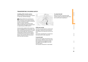 41
41 42
42 43
43 44
44 45
45 46
46 47
47 48
48 49
49 50
50 51
51 52
52 53
53 54
54 55
55 56
56 57
57 58
58 59
59 60
60 61
61 62
62 63
63 64
64 65
65 66
66 67
67 68
68 69
69 70
70 71
71 72
72 73
73 74
74 75
75 76
76 77
77 78
78 79
79 80
80 81
81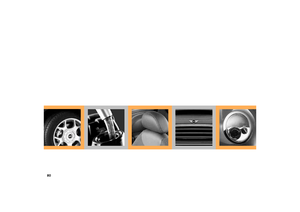 82
82 83
83 84
84 85
85 86
86 87
87 88
88 89
89 90
90 91
91 92
92 93
93 94
94 95
95 96
96 97
97 98
98 99
99 100
100 101
101 102
102 103
103 104
104 105
105 106
106 107
107 108
108 109
109 110
110 111
111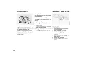 112
112 113
113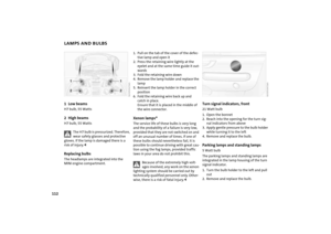 114
114 115
115 116
116 117
117 118
118 119
119 120
120 121
121 122
122 123
123 124
124 125
125 126
126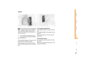 127
127 128
128 129
129 130
130 131
131 132
132 133
133 134
134 135
135 136
136 137
137 138
138 139
139 140
140 141
141 142
142 143
143 144
144 145
145 146
146 147
147 148
148 149
149 150
150 151
151

