Page 113 of 152

111
OVERVIEW REPAIRSOPERATION CONTROLS DATA INDEX
WIPER BLADES LAMPS AND BULBS Rear window wiper 1. Rotate the wiper arm completely out
from the windshield
2. Turn the wiper blade as far as it will go
to the rear, see arrow
3. Press the wiper blade against the limit
and thus out of the mounting
4. Press the new wiper blade into the
mounting.
Lamps and bulbs are an important compo-
nent of vehicle safety. Therefore, proceed
carefully when handling bulbs. The manu-
facturer of your MINI recommends that you
have such work performed by your MINI
Dealer if you are not familiar with the pro-
cedures.
Do not touch the glass portion of a
new bulb with your bare hands since
even small amounts of impurities burn into
the surface and reduce the service life of
the bulb. Use a clean cloth, paper napkin, or
similar material, or hold the bulb by its
metallic base.<
A replacement bulb set is available at your
MINI Dealer.
Whenever working on the electrical
system, switch off the electrical
accessory you are working on or disconnect
the cable from the negative terminal of the
battery. Failure to do this could result in
short circuits.
To prevent injuries and damage, comply
with any instructions provided by the bulb
manufacturer.<
Page 114 of 152

112
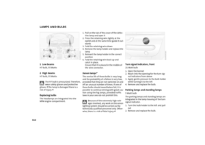
LAMPS AND BULBS1Low beamsH7 bulb, 55 Watts2High beams H7 bulb, 55 Watts
The H7 bulb is pressurized. Therefore,
wear safety glasses and protective
gloves. If the lamp is damaged there is a
risk of injury.
MINI engine compartment.
1. Pull on the tab of the cover of the defec-
tive lamp and open it
2. Press the retaining wire lightly at the
eyelet and at the same time guide it out-
wards
3. Fold the retaining wire down
4. Remove the lamp holder and replace the
lamp
5. Reinsert the lamp holder in the correct
position
6. Fold the retaining wire back up and
catch in place.
Ensure that it is placed in the middle of
the wire connector.Xenon lamps* The service life of these bulbs is very long
and the probability of a failure is very low,
provided that they are not switched on and
off an unusual number of times. If one of
these bulbs should nevertheless fail, it is
possible to continue driving with great cau-
tion using the fog lamps, provided traffic
laws in your area do not prohibit this.
Because of the extremely high volt-
ages involved, any work on the xenon
lighting system should be carried out by
technically qualified personnel only. Other-
wise, there is a risk of fatal injury.<
Turn signal indicators, front 21 Watt bulb
1. Open the bonnet
2. Reach into the opening for the turn sig-
nal indicators from above
3. Apply gentle pressure to the bulb holder
while turning it to the left
4. Remove and replace the bulb.Parking lamps and standing lamps 5 Watt bulb
The parking lamps and standing lamps are
integrated in the lamp housing of the turn
signal indicator.
1. Turn the bulb holder to the left and pull
out
2. Remove and replace the bulb.
Page 115 of 152
113
OVERVIEW REPAIRSOPERATION CONTROLS DATA INDEX
LAMPS AND BULBSSide turn signal indicators 5 Watt bulb
1. Press lamp toward vehicle tailgate and
remove
2. Remove and replace the bulb.Side marker lamps3 Watt bulb
Side marker lamps in the wheelhouse pan-
eling of the bumper.
Please contact a MINI Dealer in case of a
malfunction.
Fog lamps*H11 bulb, 55 Watts
Please contact a MINI Dealer in case of a
malfunction.
Tail lampsRear lamp 3: bulb 21/5 Watts
Other bulbs: 21 Watts
1Rear fog lamp
*
red
2Turn signal indicator yellow
3Rear lamp red
4Rear lamp/Brake lamp red
Page 116 of 152

114
LAMPS AND BULBSTo make this clear, the illustration shows a
dismantled tail lamp with the bulb holder
removed. All of the bulbs are integrated in
the bulb holder.
To reach the bulb holder, remove the cover
of the side trim panel in the cargo area. Replacing bulbs 1. Unplug the power supply
2. Release the bulb holder, arrow, and
remove
3. Apply gentle pressure to the bulb while
turning it to the left
4. Remove and replace the bulb
5. Plug in the power supply receptacle
6. Press the bulb holder into position until
you hear it engage.
Backup lamp With the space-saver spare tire option:
Access to the lamp via the back or under-
side of the bumper.
1. Press the clips together
2. Push the lamp out of the bumper
3. Apply gentle pressure to the bulb while
turning it to the left
4. Remove and replace the bulb.
Other equipment:
Please contact a MINI Dealer in case of a
malfunction.
Center high-mount brake lamp LED strip on the tailgate.
Please contact a MINI Dealer in case of a
malfunction.
Page 117 of 152
115
OVERVIEW REPAIRSOPERATION CONTROLS DATA INDEX
LAMPS AND BULBSLicense plate lamps 5 Watt bulb
1. Apply a screwdriver to the recess and
lever out the lamp cover
2. Replace the bulb.
Interior lamps 6 Watt xenon bulb
1. Press out the lamp cover with a screw-
driver
2. Remove and replace the bulb.Reading lamps2 x 6 Watt xenon bulbs
1. Press out the lamp cover with a screw-
driver
2. Unscrew the entire lamp with a screw-
driver
3. Remove the bulb from above and
replace.
Illuminated vanity mirror Lamps in the vanity mirror in the sun visor.
Please contact a MINI Dealer in case of a
malfunction.
Page 118 of 152

116
LAMPS AND BULBS REPAIRING A FLAT TIRE Cargo area lamps 5 Watt bulb
1. Press the lamp cover to the left and out
with a screwdriver.
2. Remove and replace the bulb.
Footwell lamps5 Watt bulb
1. Press out the lamp cover with a screw-
driver
2. Remove and replace the bulb.Glove compartment lamp5 Watt bulb
1. Press out the lamp cover with a screw-
driver
2. Remove and replace the bulb.Safety measures in the event of a flat
tire:
Stop the vehicle as far as possible from
passing traffic. Switch on the hazard warn-
ing flashers.
Turn the steering wheel to the straight-
ahead wheel position and engage the
steering lock. Engage the parking brake and
shift into 1st or reverse gear – selector lever
in P.
All passengers should be outside the vehi-
cle and well away from your immediate
working area – behind a guardrail, for
instance.
If a portable hazard warning lamp is avail-
able, set it up on the roadside at an appro-
priate distance from the rear of the vehicle.
Comply with all safety guidelines and regu-
lations.<
In the event of a flat tire, different proce-
dures should be followed depending on the
equipment included in your MINI:
>Vehicles with Run Flat tires, refer to
page 93
>Vehicles with a space-saver spare tire,
refer to the following section
>Vehicles with MINI Mobility System,
refer to page 121.
Page 119 of 152

117
OVERVIEW REPAIRSOPERATION CONTROLS DATA INDEX
CHANGING TIRES: MINI WITH SPACE-SAVER SPARE TIRE
*
Additional safety measures in the
event of a wheel change:
Change the wheel only on a level, firm sur-
face which is not slippery.
The vehicle or the jack could slip sideways
on soft or slippery support surfaces, such as
snow, ice, flagstones, etc..
Do not use a wooden block or similar object
as a support base for the jack, as this would
prevent it from extending to its full support
height and reduce its load-carrying capac-
ity.
Do not lie under the vehicle or start the
engine when the vehicle is supported by
the jack – risk of fatal injury.<
To change a space-saver tire, proceed as
follows:
>Remove space-saver spare tire, refer to
the section after the next one
>Prepare for tire change, refer to page 119
>Jack up the vehicle, refer to page 119
>Fit the space-saver spare tire, refer to
page 120
>Tighten the lug bolts, refer to page 120
>Drive with space-saver spare tire, refer to
page 120.
Tire change set On vehicles with a space-saver spare tire,
the tire change set is stored in the cargo
area under the floor mat.
1Chock, folding
2Hubcap remover
3Wheel stud wrench
4Jack
5Lug wrench
6Towing eyelet
7Lifting handle
The onboard tool kit includes a pouch with
a plastic bag in which you can place the
damaged wheel.
Removing the space-saver spare tireThe screw connection of the space-saver
spare tire is in the cargo area under the
floor mat, on the base of the storage com-
partment for the tire change set.
1. Loosen the screw connection using the
wheel lug bolt wrench
2. Take out the cover panel
Page 120 of 152
118
CHANGING TIRES: MINI WITH SPACE-SAVER SPARE TIRE
*
3. Screw the lifting handle from the
onboard tool kit onto the thread
4. Raise the lifting handle slightly
5. Squeeze the securing springs
6. The space-saver spare tire is released
and must be held by the lifting handle
7. Lower the space-saver spare tire with
the lifting handle
8. Unscrew the lifting handle again
9. Pull out the space-saver spare tire
towards the rear underneath the vehi-
cle
10. Position the space-saver spare tire with
the valve facing upwards
11. Unscrew the valve extension from the
valve of the space-saver spare tire
12. Unscrew the dust cap from the exten-
sion and attach to the valve on the
spare tire.
Due to its different dimensions, the
damaged wheel cannot be placed in
the recess for the space-saver spare tire.<