Page 344 of 4264

5A-28 BRAKE CONTROL SYSTEM
Isolation Valve Test
Purpose: The purpose of this test is to detect brake
pipe and valve line harness wire for wrong connections
and valve trouble.
This test will help you confirm the result of your repair
service including the removal/reinstallation of brake
pipe, valve line harness and valve.
Test conditions: The ignition key is in the “ON” position
with the four wheels lifted up. The brake pedal is
stepped on, released and stepped on again with the
parking brake released.
Test procedure:
1. Connect Tech 2 with the vehicle, and select
Actuaor Test from the menus.
2. Select a Solenoid Valve Test Menu from the
Actuaor Test Menus.
060L300002
3. Select Isolation Valve from the Valve Select Menus.
4. Step on the brake pedal.
5. Release the brake pedal.
6. Make sure that the Isolation Valve “ON” aimed at by
Tech 2 and the wheel locked position are the same.
If different, check brake pipe, valve line harness
wiring and H/UNIT. Repair is needed if abnormality
is found.
7. Conduct Step 2 through Step 5 above on all the
four wheels.
060L300002
CAUTION: When conducting this test, please
observe the following cautions.
1. Do not start the engine.
2. Lift up the vehicle at a level floor.
�
�� � Secure a clearance from the floor surface
enough to allow the lifted tire to rotate.
3. Maintain the lift up.
4. Wipe the floor surface to remove water and oil
so that the surface may become unslippery.
5. Do not load the vehicle.
�
�� � When lifting up the vehicle, be sure to
observe the lifting up points. Refer to
vehicle lifting points in 0A section.
Page 345 of 4264

BRAKE CONTROL SYSTEM 5A-29
Dump Valve Test
Purpose: The purpose of this test is to detect brake
pipe and valve line harness wire for wrong connections
and valve trouble.
This test will help you confirm the result of your repai
r
service including the removal/reinstallation of brake
pipe, valve line harness and valve.
Test conditions: The ignition key is in the “ON” position
with the four wheels lifted up. The brake pedal is
stepped on, released and stepped on again with the
parking brake released.
Test procedure:
1. Connect Tech 2 with the vehicle, and select
Actuator Test Function from the menus.
2. Select a Solenoid Valve Test Menu from the
Actuator Test Menus.
060L300002
3. Select Dump Valve from the Valve Select Meuns.
4. Step on the brake pedal.
5. Make sure that the Dump Valve “ON” aimed at by
Tech 2 and the wheel released position are the
same. If different, check brake pipe, valve line
harness wiring and H/UNIT. Repair is needed if
abnormality is found.
6. Conduct Step 2 through Step 5 above on all the
four wheels.
060L300002
CAUTION: When conducting this test, please
observe the following cautions.
1. Do not start the engine.
2. Lift up the vehicle at a level floor.
�
�� � Secure a clearance from the floor surface
enough to allow the lifted tire to rotate.
3. Maintain the lift up.
4. Wipe the floor surface to remove water and oil
so that the surface may become unslippery.
5. Do not load the vehicle.
�
�� � When lifting up the vehicle, be sure to
observe the lifting up points. Refer to
vehicle lifting points in 0A section.
Page 407 of 4264

ANTI-LOCK BRAKE SYSTEM 5B-1
SECTION 5B
BRAKES
ANTI-LOCK BRAKE SYSTEM
TABLE OF CONTENTS
PAGE
Service Precaution ...................................................................................................................... 5B – 2
Torque Specifications ................................................................................................................ 5B – 3
Electronic Hydraulic Control Unit ........................................................................................... 5B – 7
Electronic Hydraulic Control Unit and Associated Parts ............................................ 5B – 7
Removal .................................................................................................................................... 5B – 7
Installation ................................................................................................................................ 5B – 7
Front Wheel Speed Sensor ....................................................................................................... 5B – 8
Front Wheel Speed Sensor and Associated Parts ........................................................ 5B – 8
Removal .................................................................................................................................... 5B – 9
Inspection and Repair ........................................................................................................... 5B – 9
Installation ................................................................................................................................ 5B – 10
Rear Wheel Speed Sensor ........................................................................................................ 5B – 11
Rear Wheel Sensor and Associated Parts ....................................................................... 5B – 11
Removal .................................................................................................................................... 5B – 11
Inspection and Repair ........................................................................................................... 5B – 11
Installation ................................................................................................................................ 5B – 12
Front Speed Sensor Rotor ........................................................................................................ 5B – 13
Front Sensor Rotor and Associated Parts ....................................................................... 5B – 13
Removal .................................................................................................................................... 5B – 13
Inspection and Repair ........................................................................................................... 5B – 14
Installation ................................................................................................................................ 5B – 14
Rear Speed Sensor Rotor .......................................................................................................... 5B – 16
Rear Sensor Rotor and Associated Parts ........................................................................ 5B – 16
Removal .................................................................................................................................... 5B – 16
Inspection and Repair ........................................................................................................... 5B – 17
Installation ................................................................................................................................ 5B – 17
G-Sensor ........................................................................................................................................ 5B – 19
G-Sensor and Associated Parts ......................................................................................... 5B – 19
Page 419 of 4264
ANTI-LOCK BRAKE SYSTEM 5B-13
Front Speed Sensor Rotor
Front Sensor Rotor and Associated Parts
411R300010
Legend
1.
Sensor Rotor
2.
Hub and Disc
3.
Disc Rotor fixing Bolt
4. Hub and Disc Assembly
Removal
1. Remove the hub and disc assembly (4). (Refer to
the section Front wheel Drive).
2. Remove two disc rotor fixing bolts (3) on a diagonal.
3. Drive out the sensor rotor using a metal bar and
hammer through the two bolt holes.
�
Discard the used sensor rotor.
4. Install disc rotot fixing bolts and tighten them to the
specified torque.
Torque : 103 N�
m (10.5 kg�
m /76 lb ft)
Page 421 of 4264
ANTI-LOCK BRAKE SYSTEM 5B-15
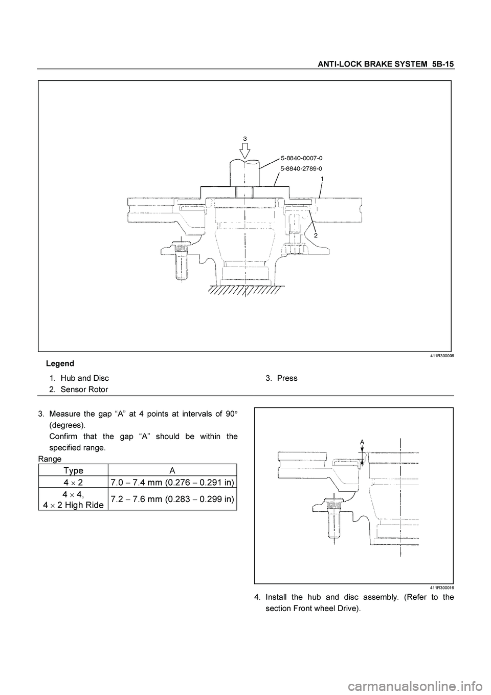
411R300006
Legend
1.
Hub and Disc
2.
Sensor Rotor
3.
Press
3.
Measure the gap “A” at 4 points at intervals of 90�
(degrees).
Confirm that the gap “A” should be within the
specified range.
Range
Type A
4
�
2 7.0 �
7.4 mm (0.276 �
0.291 in)
4
�
4,
4
�
2 High Ride 7.2
� 7.6 mm (0.283
� 0.299 in)
411R300016
4. Install the hub and disc assembly. (Refer to the
section Front wheel Drive).
Page 422 of 4264
5B -16 ANTI-LOCK BRAKE SYSTEM
Rear Speed Sensor Rotor
Rear Sensor Rotor and Associated Parts
420R300007
Legend
1.
Axle Shaft Assembly with Brake
2.
Sensor Rotor
3.
Front
Removal
1. Remove the axle shaft assembly with brake (1).
(Refer to the section Rear Axle)
Page 423 of 4264
ANTI-LOCK BRAKE SYSTEM 5B-17
A03R300003
Legend
1.
Bench Press Fitting
2.
Steel Plate (25-30 mm thickness)
3.
Axle Shaft
4.
Sensor Rotor
Inspection and Repair
Make all necessary adjustments, repairs or part
replacement.
�
Check damage or powdered iron sticking to the
sensor rotor.
�
Check play in the sensor rotor.
�
Check a broken tooth or indentation in the senso
r
rotor.
NOTE: If replacement is required remove the sensor
rotor from the axle shaft assembly with brake. (Refer to
the section Rear Axle).
�
Discard the used sensor rotor.
(Snapring, Oil seal and Bearing)
Installation
1. Install the sensor rotor and assemble it into the axle
shaft assembly with back plate. (Refer to the section
Rear Axle)
Page 424 of 4264
5B -18 ANTI-LOCK BRAKE SYSTEM
420R300005
Legend
1.
Axle Shaft
2.
Oil Seal
3.
Bolt
4.
Back Plate
5.
Sensor Rotor
6.
Double Taper Roller Bearing
2. Install the axle shaft assembly with brake in the rea
r
axle. (Refer to the section Rear Axle).


3.
Axle Shaft
4.
Sensor Rotor
Inspection and Repair
Make all necess")
