Page 496 of 4264

Adjust Nut
(2)
Clip
(3)
Bolt
(4)
Bolt
(5)
Parking Brake Cable T-end")
5D-6 PARKING BRAKE SYSTEM
This illustration is based on RHD model.
RTW35DMF000101
Legend
(1)
Adjust Nut
(2)
Clip
(3)
Bolt
(4)
Bolt
(5)
Parking Brake Cable T-end
(6)
Front Parking Brake Cable
Removal
1. Remove seat assembly and seat adjuster.
Refer to section 10.
2. Turn over the carpet so that front parking brake
cable (6) appears.
3. Remove adjust nut (1).
4. Pull out clip (2) and take out front parking brake
cable (6).
5. Remove bolt (3) (4).
6. Disconect parking brake cable T-ends (5) from
front parking brake cable (6).
7. Take out front parking brake cable through the
floor hole.
Installation
1. Apply grease (multipurpose type grease) to the
connecting portion of parking brake cable T-end
(5) and front parking brake equalizer. (arrow mark)
2. Let rear end (equalizer) of front parking brake
cable (6) enter the floor hole and connect it with
parking brake rear cable T-end (5).
3. Set front parking brake cable (6) in the parking
lever assembly.
4. Drive clip (2) into the outer cable groove of front
parking brake cable (6) at the outside of the
parking lever assembly.
5. Install bolt (3)(4) on the floor and tighten them to
the specified torque.
Torque: 15 N�
�� �m (1.5 kg�
�� �m/11 lb ft)
Page 497 of 4264
PARKING BRAKE SYSTEM 5D-7
6. Drive adjust nut (1) on the front end of front
parking brake cable (6) so that parking brake
cable T-end fits into the rear end (equalizer) o
f
front cable (6).
7. Fit the carpet on the floor.
8. Install seat adjuster and seat assembly.
Refer to section 10.
9. Pull parking brake lever with a force equivalent to
operating force: 490N (50 kg/110 lb), 10 times fo
r
conditioning.
10. Adjust nut (1) so that parking brake lever goes
through 8�
14 notches, when pulled with a
operation force of 294N (30 kg/66 lb).
11. Check brake for no drag.
Page 498 of 4264

RTW35DSF000101
Legend
(1)
Rear Floor Console
(2)
Parking Brake Cable")
5D-8 PARKING BRAKE SYSTEM
Parking Brake Lever
Parking Brake Lever Assembly and Associated Parts (Bucket Seat)
RTW35DSF000101
Legend
(1)
Rear Floor Console
(2)
Parking Brake Cable T-end
(3)
Adjust Nut
(4)
Switch
(5)
Parking Brake Lever Assembly
(6)
Bolt
(7)
Equalizer
Removal
1. Remove rear floor console (1).
Refer to section 10.
2. Loosen adjust nut (3).
3. Remove bolt (6).
4. Remove switch (4).
5. Disconnect parking brake cable T-end (2) from
parking brake lever assembly (5).
6. Take out parking brake lever assembly (5).
Installation
1. Apply grease (multipurpose type grease) to the
connecting portion of parking brake rear cable T-
end (2) and parking brake lever equalizer (7).
(arrow mark)
2. Connect parking brake rear cable T-end (2) to
equalizer (7).
3. Install switch (4).
4. Tighten the parking brake lever fixing bolt (6) to
the specified torque.
Torque: 15 N�
�� �m (1.5 kg�
�� �m/11 lb ft)
5. Drive adjust nut (3) on parking brake assembly so
that parking brake cable T-end fits into equalize
r
(7).
6. Install rear floor console (1).
Refer to section 10.
7. Pull parking brake lever with a force equivalent to
operating force: 490 N (50 kg/110 lb), 10 times fo
r
conditioning.
8.
Adjust nut (3) so that parking brake lever goes
through 6�
8 notches, when pulled with a operation
force of 294 N (30 kg/66 lb).
9. Check brake for no drag.
Page 507 of 4264
WORKSHOP MANUAL
TF SERIES
CAB
SECTION 10
Page 509 of 4264

CAB 10-1
SECTION 10
CAB
TABLE OF CONTENTS
PAGE
Windshield.......................................................................................................................... 10- 2
Rear Window Assembly .................................................................................................... 10- 7
Front Door Assembly ........................................................................................................ 10- 10
Rear Door Assembly (Crew Cab) ...................................................................................... 10- 20
Instrument Panel................................................................................................................ 10- 28
Floor Console..................................................................................................................... 10- 34
Console Box (Without Floor Console) ............................................................................. 10- 38
Headlining .......................................................................................................................... 10- 39
Interior Trim Panels ...........................................................................................................10- 44
Fuel Filler Lid Opener Lever/Cable................................................................................... 10- 55
Quarter Glass (Extend Cab) .............................................................................................. 10- 70
Font Seat ............................................................................................................................ 10- 71
Rear Seat (Crew Cab) ........................................................................................................ 10- 74
Jump Seat (Extend Cab) ................................................................................................... 10- 75
Front Seat Belt ................................................................................................................... 10- 76
Rear Seat Belt (Crew Cab) ................................................................................................ 10- 80
Rear Seat Belt (Extend Cab) ............................................................................................. 10- 84
Front Wheel Extension ...................................................................................................... 10- 87
Rear Wheel Extension ....................................................................................................... 10- 88
Tail Gate Assembly ............................................................................................................ 10- 89
Page 537 of 4264
CAB 10-29
Important Operations
1. Front Console Assembly
�
Refer to Floor Consol in this section.
2. Glove Box
�
Remove 2 fixing screws and pulling the handle.
3. Instrument Panel Driver Lower Cover Assembly
1) Remove the engine hood opener 2 fixing screws.
2) Remove the lower cover one fixing screw.
3) Pull out the cover (Stick type parking brake only).
4) Pull out the lower cover assembly.
4. Driver Knee Bolster Assembly
�
Remove 4 fixing bolts.
Caution:
For precaution on installation or removal of SRS-air bag
system, refer to section 9 “Supplemental Restraint System
(SRS) - AIR BAG”
5. Driver Air Bag
6. Steering Wheel/Steering Cowl
�
Refer to Section 3B “STEERING COLUMN” for steering
lock assembly removal steps.
7. Meter Cluster Assembly
�
Pull out the 4 clip positions.
Page 539 of 4264
CAB 10-31
13.Ashtray Case
� Pull out the ashtray case.
14. Center Cluster Assembly
1) Pull out the cluster at the 6 clip positions.
2) Disconnect the cigarette lighter, accessory socket,
hazard switch and clock connectors.
15. Control Lever Assembly
�
Remove the 2 fixing screws.
17.Ashtray Bracket
�
Remove the 3 fixing screws and illumination connector.
Caution:
For precautions on installation or removal of SRS-air bag
system, refer to section 9 "Supplemental Restraint System
(SRS) - AIR BAG".
21. Passenger Air Bag
�
Remove 2 fixing bolts, 2 fixing nuts and connector.
22. Side Ventilation Grille.
� Pull out the grilles and disconnect switch connecto
r
(Driver’s side).
23. Vent Duct Assembly/Defroster Nozzle Assembly
�
Refer to section 1 “HVAC” for defroster nozzle and
ventilation duct removal steps.
25. Instrument Panel
�
Remove the clip and 6 fixing bolts.
26. Cross Beam
Page 550 of 4264
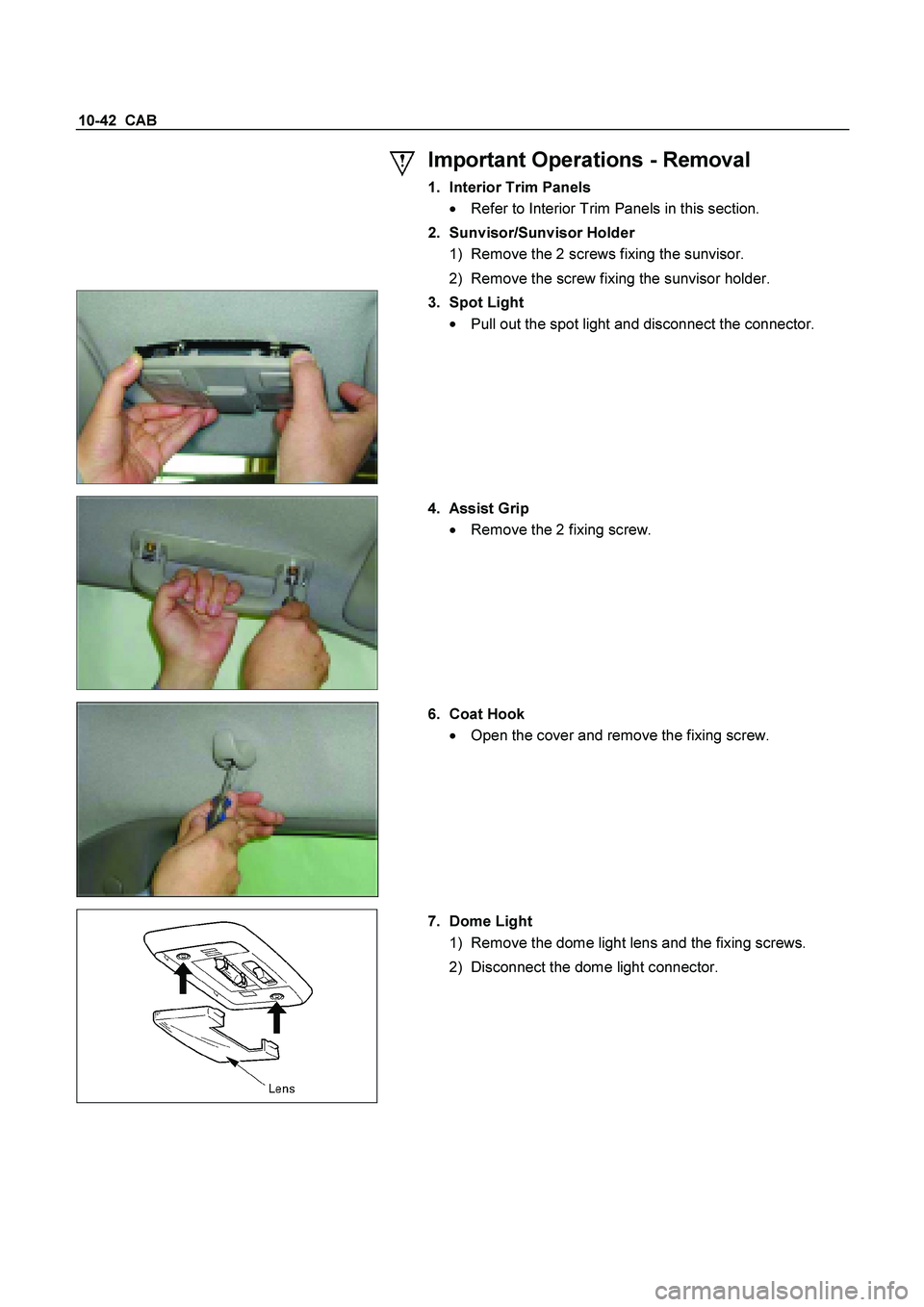
10-42 CAB
Important Operations - Removal
1. Interior Trim Panels
�
Refer to Interior Trim Panels in this section.
2. Sunvisor/Sunvisor Holder
1) Remove the 2 screws fixing the sunvisor.
2) Remove the screw fixing the sunvisor holder.
3. Spot Light
�
Pull out the spot light and disconnect the connector.
4. Assist Grip
�
Remove the 2 fixing screw.
6. Coat Hook
� Open the cover and remove the fixing screw.
7. Dome Light
1) Remove the dome light lens and the fixing screws.
2) Disconnect the dome light connector.
 on the front end of front
parking brake cable (6) so that parking brake
cable T-end fits into the rear end (equalizer) o
f
front cable (6).
7. Fi")