Page 3230 of 4264
7B1-66 MANUAL TRANSMISSION
6. Remove gear control lever (5).
7. Raise and support vehicle with suitable stands.
8. Remove rear propeller shaft (6).
NOTE: Apply alignment marks on the flange at the
differential side.
9. Remove front propeller shaft (7).
NOTE: Apply alignment marks on the flange at both
front and rear sides.
401RS023
10. Loosen the front exhaust pipe fixing nuts (8) at the
engine side but not remove them. (Diesel engine
only)
150R300004
11. Remove the exhaust pipe (9). (6VE1 only)
RTW37ASH000101
12. Disconnect harness connectors and clips on the
transfer.
�
Actuator connector
�
Car Speed Sensor
810R300069
Legend
(1) Neutral Switch Connector: Transmission
(2) Back up Switch Connector
(3) Speed Sensor Connector
(4) Actuator Connector
(5) 2W - 4W Switch Connector
(6) Neutral Switch Connector: Transfer
Page 3238 of 4264
7B1-74 MANUAL TRANSMISSION
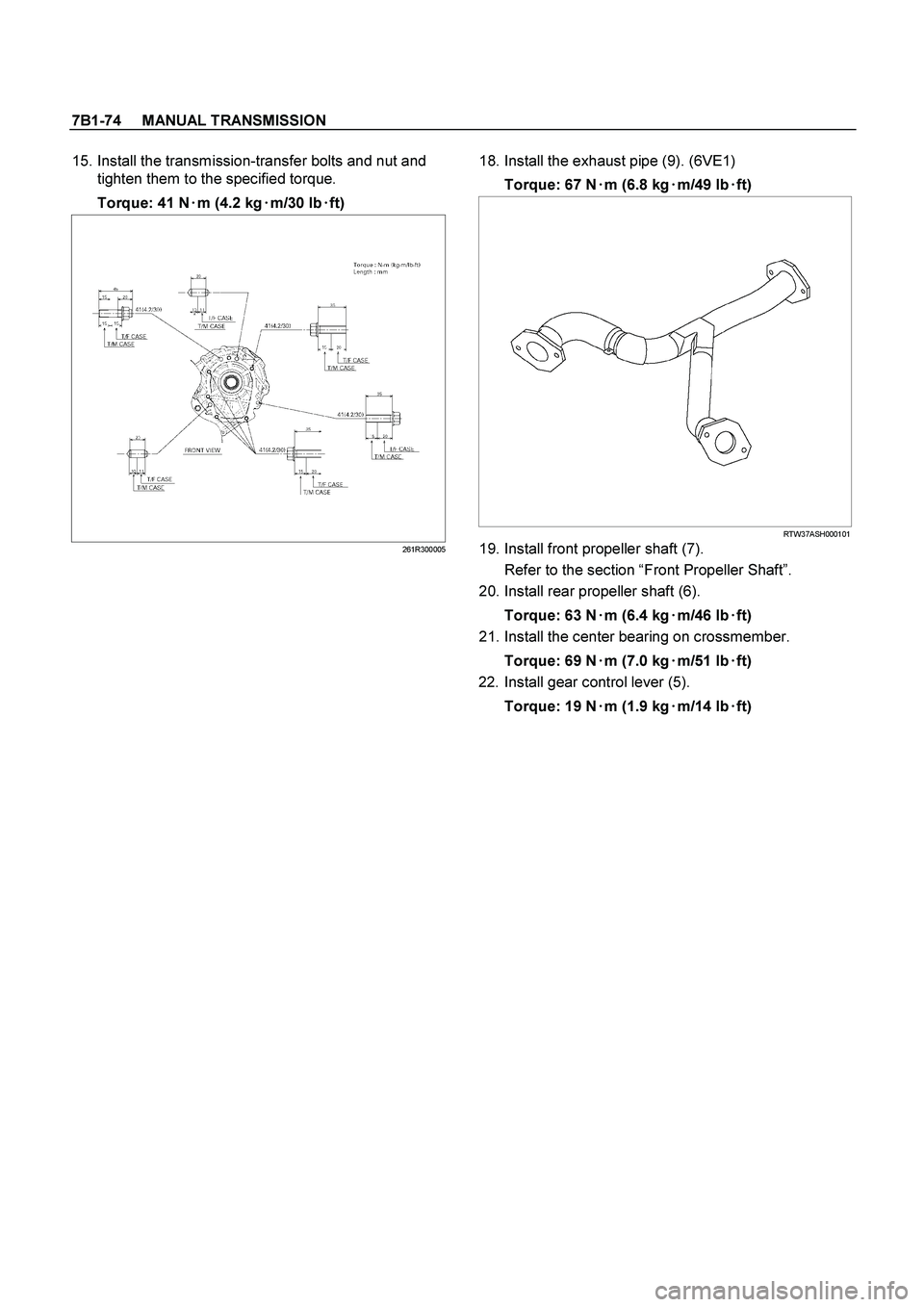
15. Install the transmission-transfer bolts and nut and
tighten them to the specified torque.
Torque: 41 N�
�� �
m (4.2 kg�
�� �
m/30 lb�
�� �
ft)
261R300005
18. Install the exhaust pipe (9). (6VE1)
Torque: 67 N�
�� �m (6.8 kg�
�� �m/49 lb�
�� �ft)
RTW37ASH000101
19. Install front propeller shaft (7).
Refer to the section “Front Propeller Shaft”.
20. Install rear propeller shaft (6).
Torque: 63 N�
�� �m (6.4 kg�
�� �m/46 lb�
�� �ft)
21. Install the center bearing on crossmember.
Torque: 69 N�
�� �m (7.0 kg�
�� �m/51 lb�
�� �ft)
22. Install gear control lever (5).
Torque: 19 N�
�� �
m (1.9 kg�
�� �
m/14 lb�
�� �
ft)
Page 3592 of 4264
7D-4 TRANSFER CASE
Transfer Rear Oil Seal
Transfer Rear Oil Seal and Associated Parts
220R300018
Legend
(1) Rear Propeller Shaft
(2) Oil Seal
Removal
1.
Disconnect the rear propeller shaft (1) from the
transfer case side.
2.
Remove the oil seal from the transfer case.
Installation
1.
Install oil seal and apply engine oil to the oil seal
outer surfaces.
2.
Apply the recommended grease (BESCO L2) or
equivalent to the oil seal lip.
3.
Use the oil seal installer 5-8840-2786-0 to install the
rear seal (2) to the transfer rear case.
Page 3593 of 4264
TRANSFER CASE 7D-5
220R300021
4.
Connect the rear propeller shaft.
Page 3594 of 4264
7D-6 TRANSFER CASE
Transfer Case Assembly
Transfer Case Assembly and Associated Parts
RTW47DLF000501
Legend
(1) Rear Propeller Shaft
(4)
Center Exhaust Pipe (6VE1 only)
(2) Front Propeller Shaft
(3) Transfer Case Assembly
Page 3595 of 4264

TRANSFER CASE 7D-7
Removal
NOTE: Before removing transmission and transfer
assembly from vehicle, change the transfer mode to
2WD using the 4WD push button switch on dash panel.
1.
Disconnect battery ground cable.
2.
Raise and support vehicle with suitable stands. Drain
transfer case fluid.
3. Remove the center exhaust pipe(5). (6VE1 only)
4.
Remove rear propeller shaft (1) and front propelle
r
shaft (2)(3).
NOTE: Apply alignment marks on the flange at both
front and rear sides.
5.
Disconnect harness connectors and clip.
Connector: transfer switch, 2WD-4WD actuator,
speed sensor.
NOTE: Avoid turning the vehicle ignition switch to the
ON position when the 2WD-4WD connector is removed
(battery connected).
If the ignition switch must be turned to the ON position,
the controller must first be removed (memory must be
cleared because the CHECK 4WD INDICATOR will
light).
6.
Remove transfer case (4) from the vehicle.
Installation
1.
Apply a thin coat of molybdenum disulfide grease to
the input shaft spline as shown in the figure.
260R300001
Page 3597 of 4264
TRANSFER CASE 7D-9
For A/T
261R300002
3.
Connect harness connectors and clip.
Connector: transfer switch, 2WD-4WD actuator,
speed sensor.
4. Install center exhaust pipe(5). (6VE1 only)
5.
Install rear propeller shaft (1) and front propelle
r
shaft (2)(3).
Torque: 63 N�
�� �m (6.4 kg�
�� �m/46 lb ft)
Page 3630 of 4264
, 4-wheel drive high-speed (4H), 4-wheel drive low-
speed (4L)")
7D1-4 TRANSFER CONTROL SYSTEM
Summary of transfer control system
The transfer control system switches between the 2-wheel
drive (2H), 4-wheel drive high-speed (4H), 4-wheel drive low-
speed (4L), and neutral positions electrically when the driver
operate the switches.
This system has following functions.
1. Connection or disconnection of drive force distribution to
the front wheel front shaft (axle shaft) (The drive force
distribution to the front propeller is connected o
r
disconnected with the motor actuator.)
2. Try to repeat the connection or disconnection of the front
wheel drive function as described above.
3. Option: Shift on the fly type only.
Instruction of connection or disconnection of the drive force
transmission between the front wheel axle (axle shaft) and
front wheel
(The motor actuator connects or disconnects the left front
wheel ad front wheel axle (axle shaft).).
4. Shifting of auxiliary transmission gears, connection o
r
disconnection of wheel and engine drive force (4H, 4L,
neutral).
5. Operation of indicator on the instrument panel.
6. Transmission of position signal to other controllers.
.
7. Raise and support vehicle with suitable stands.
8. Remove rear propeller shaft (6).
NOTE: Apply alignment marks on the fl")
 Rear Propeller Shaft
(2) Oil Seal
Removal
1.
Disconnect the re")

 Rear Propeller Shaft
(4)
Center Exhaust Pipe (6VE1 only)
(2) Front")
. (6VE1 only)")