Page 3772 of 4264

Evaluation
i. If there is no 1 �
2 upshift:
Solenoid S2 is stuck
1 –2 shift valve is stuck
ii. If there is no 2 �
3 upshift:
")
7A3-16 ON-VEHICLE SERVICE (AW30 –40LE)
Evaluation
i. If there is no 1 �
2 upshift:
Solenoid S2 is stuck
1 –2 shift valve is stuck
ii. If there is no 2 �
3 upshift:
Solenoid S1 is stuck
2 –3 shift valve is stuck
iii. If there is no 3 �
OD upshift (throttle valve opening
1/2):
Solenoid S2 is stuck
3 –OD shift valve is stuck
iv. If the shift point is defective: Refer to TROUBLESHOOTING CHART in this
section.
v. If the lock-up is defective: Refer to TROUBLESHOOTING CHART in this
section.
2. In the same manner, check the shock and slip at the 1 �
2, 2 �
3 and 3 �
OD upshifts.
NOTE: Drive the vehicle on level ground.
Evaluation
If the shock is excessive:
Refer to TROUBLESHOOTING CHART in this section.
3. Run at “D" range lock-up or OD gear and check fo
r
abnormal noise and vibration.
NOTE: The check for the cause of abnormal noise and
vibration must be made with extreme care as it could
also be due to loss of balance in the propeller shaft,
differential, the torque converter, etc. or insufficient
bending, rigidity, etc. in the power train.
RUW37ASH000201
4. While running in “D" range, 2nd, 3rd gears and OD,
check to see that the possible kick-down vehicle
speed limits for 2 �1, 3 �1, 3 �2, OD �3 and
OD �
2 kick-downs conform to those indicated on
the automatic shift diagram.
RUW37AMH000101
5. Check for abnormal shock and slip at kick-down.
6. While running in “D" range, OD gear or “lock-up",
shift to “2" and “L" ranges and check the engine
braking effect at each of these ranges.
7. Also check to see that downshift is made from 3 �
2
or from OD to 3 and then to 2 immediately and that
2 �
1 downshift point is within the limits shown in the
diagram when tested by releasing the accelerato
r
pedal and shifting into position of “L" while driving in
the third gear or in overdrive.
Page 3796 of 4264
7A3-40 ON-VEHICLE SERVICE (AW30 –40LE)
Rear Oil Seal (Adapter Housing, 4�
� �
�4)
Removal
1. Remove the front and rear propeller shaft assembly
from the transfer case.
2. Remove the transfer case assembly from the transmission case.
Refer to Section 4 DRIVELINE/AXLE.
3. Using a screwdriver, remove the rear oil seal.
Installation
1. Apply ATF to a new rear oil seal lip.
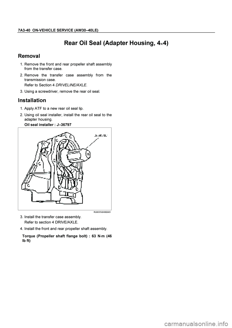
2. Using oil seal installer, install the rear oil seal to the adapter housing.
Oil seal installer : J –36797
RUW37ASH002401
3. Install the transfer case assembly.
Refer to section 4 DRIVE/AXLE.
4. Install the front and rear propeller shaft assembly.
Torque (Propeller shaft flange bolt) : 63 N �
��
�
m (46
Ib ft)
Page 3797 of 4264
ON-VEHICLE SERVICE (AW30 –40LE) 7A3-41
Rear Oil Seal (Extension Housing, 4�
� �
�2)
Removal
1. Remove the rear propeller shaft assembly.
2. Using a screwdriver, remove the rear oil seal.
Installation
1. Apply ATF to a new rear oil seal lip.
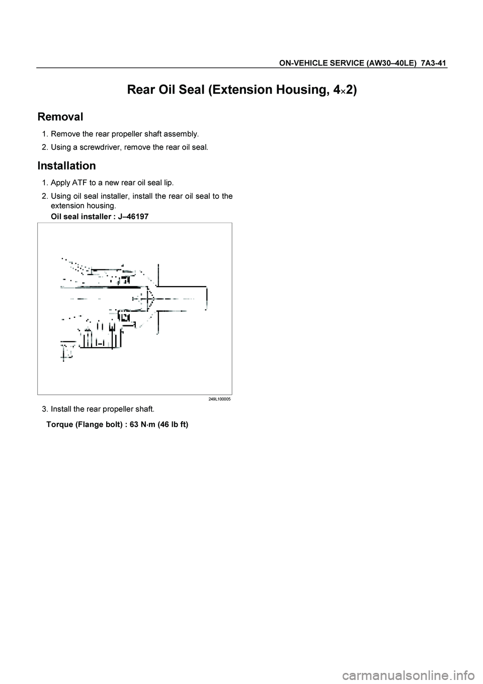
2. Using oil seal installer, install the rear oil seal to the extension housing.
Oil seal installer : J –46197
249L100005
3. Install the rear propeller shaft.
Torque (Flange bolt) : 63 N �
��
�
m (46 Ib ft)
Page 3798 of 4264
7A3-42 ON-VEHICLE SERVICE (AW30 –40LE)
Transmission Assembly
Transmission and Associated Parts
Legend
(9) Under Cover
(1) Rear Propeller Shaft (10) Flex Plate Torque Converter bolt
(2) Front Propeller Shaft (4WD only) (11) Shift Cable
(3) Middle Exhaust Pipe (12) Rear Mount Rubber
(4) Transfer Case Assembly (4WD only) (13) Heat Protector
(5) Fuel Pipe Clip and Bracket (14) Transmission Crossmember
(6) ATF Pipe and Clip (15) Transmission Assembly (2WD)
(7) Oil Level Gauge and Guide Tube (16) Transmission Assembly (4WD)
(8) Suspension Crossmember
Page 3799 of 4264
 7A3-43
Removal
NOTE: Before removing transmission and transfer
assembly from vehicle, change the transfer mode to
2WD using the 4WD push button switch on dash")
ON-VEHICLE SERVICE (AW30 –40LE) 7A3-43
Removal
NOTE: Before removing transmission and transfer
assembly from vehicle, change the transfer mode to
2WD using the 4WD push button switch on dash panel.
1. Disconnect battery ground cable.
2. Raise and support vehicle with suitable stands.
3. Remove front propeller shaft.(4WD only)
NOTE: Apply alignment marks on the flange at both
front and rear sides.
4. Remove rear propeller shaft.
NOTE: Apply alignment marks on the flange at the
differential side.
401RS023
5. Remove the middle exhaust pipe.
RTW37ASH0001
6. Disconnect the transfer harness connectors and the
clips.(4WD only)
Speed sensor
2W-4W shift actuator
NOTE: Avoid turning the vehicle ignition switch to the
ON position when the 2WD-4WD connector is removed
(battery connected).
If the ignition switch must be turned to the ON position,
the controller must first be removed (memory must be
cleared because the CHECK 4WD INDICATOR will
light).
7. Support transfer case with a transmission jack.(4WD only)
8. Remove the transfer case assembly from the
transmission.(4WD only)
9. Disconnect the shift cable.
10. Remove the fuel pipe clips with the fuel pipes from the brackets and put aside it. Remove the fuel pipe
brakets from the transmission.
P1010010
11. Discinnect the transmission harness connectors
and clips.
12. Remove the oil level gauge and the guide tube.
13. Remove the suspension crossmember.
Page 3805 of 4264
ON-VEHICLE SERVICE (AW30 –40LE) 7A3-49
Tighten transmission transfer bolts as shown in
the figure.(4WD only)
261R300002
20. Connect transfer harness connectors and
clips.(4WD only)
Speed sensor
2W-4W shift actuator
21. Install the middle exhaust pipe.
RTW37ASH0001
22. Install the rear propeller shaft.
Torque: 63 N �
��
�
m (6.4 kg �
��
�
m/46 lb ft)
NOTE: Align alignment marks on the flange.
23. Install the center bearing on crossmember.
Torque: 69 N �
��
�
m (7.0 kg �
��
�
m/51 lb ft)
24.Install the front propeller shaft.(4WD only)
Torque: 63 N �
��
�
m (6.4 kg �
��
�
m/46 lb ft)
NOTE: Align alignment marks on the flange.
401RS023
25. Connect battery ground cable.
Page 3956 of 4264

7A1-10 CONSTRUCTION AND FUNCTION
INPUT SHAFT
� The input shaft has some oil holes, through which lubricating ATF is supplied to the torque converter,
bearings, etc.
� The input shaft is fitted the turbine runner in the torque converter, reverse & high clutch drum and rear sun
gear by means of the spline. Therefore, the engine driving force received by the torque converter is
transmitted to the reverse & high clutch drum and rear sun gear.
OUTPUT SHAFT
� The output shaft has some oil holes, through which the lubricating ATF is supplied to the bearings,
planetary gear unit, etc.
� The output shaft transmits the engine driving force from the planetary gear to the propeller shaft.
� The front internal gear is fitted with the rear carrier assembly by spline. The parking gear is also fitted by
spline. By fixing this gear mechanically, the output shaft is fixed as required when parking the vehicle.
GEAR SHIFTING MECHANISM
� The JR405E consists of two sets of planetary gears, three multiple plate clutches, two multiple plate
brakes and a one-way clutch. They are activated in different combinations in any of four forward and one
reverse gear positions.
Principle of gear shifting (Figure 12)
� Planetary gears have the advantage of a compact configuration because of the way they are constructed
with a single central shaft.
� Also, unlike the manual transmission gears that require changing of gear mesh, the gear ratio of the
planetary gears can be changed more easily by locking, releasing or rotating only some of their parts.
� A planetary gear is made up of a sun gear (1) at its center and pinion gears (2) each of which rotates
about its own center and also along the sun gear, as shown. They are all called in the internal gear (3).
� Also, since the pinion gears are further supported by the planetary carrier (4), they rotate as a unit in the
same direction and at the same rate.
� As shown above, each planetary gears are constructed of three elements; a sun gear, pinion gears, and
internal gear and a planetary carrier. Gear shifting is achieved by conditioning two of the three elements
namely the sun gear, internal gear and the planetary carrier.
� The planetary gears are locked by the clutch, brake and one-way clutch according to the gear shifting.
1. Sun Gear
2. Pinion Gear
3. Internal Gear
4. Planetary Carrier
Figure 12. Planetary Gear
Page 4099 of 4264
 7A2-107
No. B10: Brake is Applied in R Range
Description:
� Brake is applied suddenly in R range.
Diagnosis Hints:
� Basically a trouble in the AT main unit. However, s")
DIAGNOSIS (JR405E) 7A2-107
No. B10: Brake is Applied in R Range
Description:
� Brake is applied suddenly in R range.
Diagnosis Hints:
� Basically a trouble in the AT main unit. However, some trouble in the sensor system or output system may have
some influence on the trouble in the main unit and therefore these systems should be also checked to prevent
reproduce of the trouble.
Possible Cause:
� Seized clutch (low clutch, high clutch, 2-4 brake).
� Shortage or faulty quality of ATF.
� Trouble in control valve body (faulty operation, sticking, clogged oil passage).
� Disordered select cable (select indicator light indicates R but the hydraulic system is not in the R range).
� Malfunction of parking mechanism.
No. B11: Insufficient Starting or Shaking in D Range
Description:
� Insufficient starting or shaking in D range.
Possible Cause:
� Slip of clutch (low clutch, low one-way clutch, reverse clutch, low & reverse brake).
If slip of clutch is caused, a DTC (gear ratio error) is stored.
� Shortage or faulty quality of ATF.
� Dropped line pressure.
� Trouble in control valve body (faulty operation, sticking, clogged oil passage).
No. B12: Noise or Vibration is Generated at Starting
Description:
� Noise or vibration is generated in the vicinity of AT at starting.
Diagnosis Hints:
� Cause other than AT can be also considered. It is effective means to reproduce a running condition using a lift
up, chassis dynamo, etc. to investigate the origin (generating condition) of noise and vibration.
Caution:
Lifting up some unit to test it accompanies danger. Provide safety measures as far as possible and
carry out the test with sufficient care.
Possible Cause:
Following sources of noise or vibration other than the AT can be considered.
� Noise from differential gears.
� Noise from propeller shaft.
� The bearing support in the middle of the propeller shaft has fatigued, and the bend angle of the propeller shaft
has changed, causing vibration at the time of start.
� Unbalanced and poor uniformity of tires cause vibration.

Transmission Assembly
Transmission and Associated Parts
Legend
(9) Under Cover
(1) Rear Propeller Shaft (10) Flex Plate Torque Co")
 7A3-49
Tighten transmission transfer bolts as shown in
the figure.(4WD only)
261R300002
20. Connect transfer harness connectors and
clips.(4WD only)")