Page 217 of 4264
REAR AXLE 4B-53
4. POWER NOT BEING TRANSMITTED TO THE WHEELS
(PROPELLER SHAFT OPERATION IS NORMAL)
Checkpoint Trouble Cause Countermeasure
Replace the rear axle shaftBroken rear axle shaft NG
Replace the drive pinion and
the ring gear as a setDrive pinion and ring gearBroken drive pinion and/or ring
gear
Replace the differential gears
and/or the spiderDifferential cage gearsBroken differential cage gears
and/or spider NG NG
OK OK
Rear axle shaft
Page 223 of 4264
FRONT WHEEL DRIVE 4C1-3
MAIN DATA AND SPECIFICATIONS
FRONT AXLE AND DIFFERENTIAL
Ring gear size mm (in) 194 (7.6)
Axle tube
Type It consists of the duce, a cast iron housing and the Axle tube.
Gear type Hypoid
Gear ratio (to 1) 4.100, 4.300, 4.555, 4.777, 5125
Differential type Two pinion
Specified gear oil (APL grade) GL-5
Oil capacity liter 1.4
(US/UK gal.) (0.4/0.33)
Axle shaft type Constant velocity joint (Birfield joint type and double offset joint).
FRONT PROPELLER SHAFT mm(in)
4�
4 Model
Engine Model 4JA1-T(L) 4JA1-TC 4JH1-TC C24SE 6VE1
Transmission Type 5M/T (MUA) 5M/T
(MUA) 4A/T 5M/T
(MUA) 5M/T
(MUA) 4A/T
Front Axle 194 mm �
�
�
�
�
Outside Diameter mm 40 40 40 40 40 40
(in) (1.57) (1.57) (1.57) (1.57) (1.57) (1.57)
Inside Diameter mm 32 32 32 32 32 32
(in) (1.26) (1.26) (1.26) (1.26) (1.26) (1.26)
Length (L) mm 607 607 676 586 586 607
(in) (23.90) (23.90) (26.61) (23.07) (23.07) (23.90)
Fix Bolt Size T/F M10 M10 M10 M10 M10 M10
Axle M10 M10 M10 M10 M10 M10
Page 224 of 4264
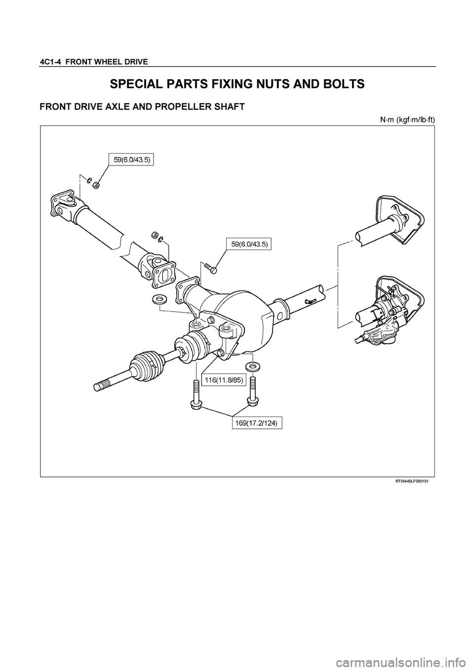
4C1-4 FRONT WHEEL DRIVE
SPECIAL PARTS FIXING NUTS AND BOLTS
FRONT DRIVE AXLE AND PROPELLER SHAFT
N�
m (kgf�
m/lb�
ft)
RTW440LF000101
Page 233 of 4264
FRONT WHEEL DRIVE 4C1-13
FRONT PROPELLER SHAFT
RTW34ASF000101
Page 234 of 4264
4C1-14 FRONT WHEEL DRIVE
FRONT DRIVE AXLE ASSEMBLY
Front Drive Axle Assembly and Associated Parts
RTW440LF000501
Legend
1. Propeller Shaft
2. Front Axle Case Assembly and Front Drive
Shaft Assembly
3. Washer
4. Mounting Bolt
5. Tie-rod End ; Steering Unit
6. Knuckle and Back Plate
7. Hub and Disc Assembly
8. Suspension Crossmember
Page 235 of 4264

FRONT WHEEL DRIVE 4C1-15
Removal
1. Jack up the vehicle and support it using jack stand.
2. Remove the tire and wheel.
3. Remove the stone guard.
4. Remove the brake caliper fixing bolt and hang the caliper.
Refer to Disc Brakes in Brake section.
5. Remove the antilock brake system speed sensor.
Refer to Front Wheel Speed Sensor in Brake section.
6. Remove the hub and disc assembly.
Refer to Front Hub and Disc in this section.
7. Remove the propeller shaft, refer to Front Propeller Shaft in
this section.
8. Loosen the height control arm of the torsion bar, then
remove the torsion bar from lower control arm.
Refer to Torsion Bar in Suspension section.
9. Remove the suspension crossmember.
10. Remove the lower nut (1) of the stabilizer link.
11. Remove the lower bolt and nut (2) of the shock absorber.
12. Remove the tie-rod end from the knuckle.
Refer to Power Steering Unit in Steering Section.
13. Disconnect the breather hose of the front axle.
14. Disconnect the actuator connector. (With shift on the fly)
15. Remove the bolts and nuts of the lower control arm (Frame
side), then disconnect the lower control arm from frame.
16. Disconnect between the right side upper control arm and
the knuckle, then remove the knuckle with lower control
arm.
CAUTION :
When removing the knuckle, be careful not to damage the
oil seal inside of the knuckle.
Page 237 of 4264

FRONT WHEEL DRIVE 4C1-17
NOTE :
Adjust the buffer clearance before tighten the bolts and nuts of
the lower control arm.
6. Install the breather hose of the front axle.
7. Install the actuator connector of the shift on the fly. (With
shift on the fly)
8. Install the tie-rod end of the power steering unit to the
knuckle, tighten the nut to the specified torque.
Torque : 98 N·m (10.0kg·m/73 lb ft)
9. Install lower bolts and nuts of the shock absorber, tighten it
to the specified torque.
Torque : 93 N·m (9.5kg·m/69 lb ft)
10. Install lower nuts of the stabilizer link, tighten it to the
specified torque.
Torque : 50 N·m (5.1kg·m/37 lb ft)
11. Install the suspension crossmember.
12. Install the torsion bar.
Refer to Torsion Bar in Suspension section.
13. Install the front propeller shaft.
Refer to Front Propeller Shaft in this section.
14. Install the hub and disc assembly and adjust the bearing
preload.
Refer to Front Hub and Disc in this section.
15. Install the wheel speed sensor of the antilock brake
system.
16. Install the brake caliper. Tighten the bolt of the caliper
bracket to the specified torque.
Torque : 155 N·m (15.8kg·m/115 lb ft)
17. Install the stone guard.
18. Install the tire and wheel.
19. Lower the vehicle, adjust the trim height.
Refer to Trim Height Adjustment in Steering section.
20. Tighten the bolts and nuts of the lower control arm to the
specified torque.
Refer to Lower Control Arm in Suspension section.
Page 287 of 4264
FRONT WHEEL DRIVE 4C1-67
TROUBLESHOOTING
Refer to this Section to quickly diagnose and repair front axle problems. Each troubleshooting chart has three
headings arranged from left to right.
(1) Checkpoint (2) Trouble Cause (3) Countermeasure
This Section is divided into ten sub-sections:
4�
�� �2 Model
1. Wanders and pulls
2. Front wheel shimmy
4�
�� �4 Model
1. Oil leak at front axle
2. Oil leak at pinion shaft
3. Noises in front axle drive shaft joint
4. Noises in front axle
5. Wanders and pulls
6. Front wheel shimmy
Propeller shaft
1. Noise
2. Vibration

Checkpoint Trouble Cause Countermeasure
Replace the rear axle shaftBroken rear axle shaf")
 194 (7.6)
Axle tube
Type It consists of the duce, a cast iron housing and the Axle tub")


")