Page 161 of 4264
 and
check for run�
out by holding the probe of a dial indicator (1) in
cont")
PROPELLER SHAFT 4A-25
401RS027
Propeller Shaft Run
�
�� �out
Support the ends of the propeller shaft on V-blocks (2) and
check for run�
out by holding the probe of a dial indicator (1) in
contact with the center part of the shaft. If the amount of run�
out is beyond the standard value for assembly, correct with a
bench press or replace the shaft with a new propeller shaf
t
assembly.
Standard: 0.3 mm (0.012 in)
Limit: 0.5 mm (0.02 in)
401RS009
Play in Splines in Normal Direction of Rotation
Check the amount of play between the sleeve yoke (1) and the
propeller shaft spline (2) in the direction of rotation, using a
pointed feeler gauge.
Standard: 0.073 �
�� � 0.156 mm (0.003 �
�� � 0.006 in)
Limit: 0.3 mm (0.012 in)
401RS010
Play in Universal Joint
Limit: Less than 0.1 mm (0.004 in)
401RS011
Reassembly
1. Install spider to flange yoke. Be sure to install the spider by
aligning the setting marks made during disassembly.
2. Apply a molybdenum�
disulfide grease or a multi�
purpose
type grease NLGI No. 2 to inside of the bearing cap.
Grease Amount: Approx. 1.2 g (0.042 oz)
Page 162 of 4264
4A-26 PROPELLER SHAFT
401RS012
3. Using either a mallet (or copper hammer) or a press, install
the needle roller bearing into the yoke so that the snap ring
can be installed in its groove.
CAUTION:
The needle roller bearing cannot be installed smoothly if it
is set at an incorrect angle with the flange and excessive
hammering will damage the needle roller bearing.
401RS028
4. Align setting marks (1) and join the yokes.
5. Install snap ring.
NOTE:
Discard used snap rings and install new ones.
When the bearing cap is in position, select and attach a snap
ring of suitable thickness so that the end play of the spider pin
is held within 0.1 mm (0.004 in).
Snap ring thickness and Identification color
1.50 mm (0.059 in); Light Blue
1.56 mm (0.061 in); Prink
1.53 mm (0.060 in); White
1.59 mm (0.063 in); Yellow
1.62 mm (0.064 in); Green
1.65 mm (0.065 in); Brown
1.68 mm (0.066 in); Not colored
NOTE:
Be sure to use snap rings of the same thickness
on both sides.
Page 163 of 4264
PROPELLER SHAFT 4A-27
Reassembly
401RW057
Legend
(1) Sleeve Yoke
(2) Seal
(3) Tube Assembly
1. Discard used seal and install new one.
2. Align the alignment marks and install tube assembly to
sleeve yoke.
Page 164 of 4264
4A-28 PROPELLER SHAFT
MEMO
Page 171 of 4264

REAR AXLE 4B-7
REAR AXLE ASSEMBLY
General Description
A03R300001
The rear axle assembly is of the semi–floating type in
which the vehicle weight is carried on the axle
housing .
The center line of the pinion gear is below the center
line of the ring gear (hypoid drive).
All parts necessary to transmit power from the
propeller shaft to the rear wheels are enclosed in a
banjo type axle housing.
The 220 mm (8.6 in) ring gear rear axle uses a
conventional ring and pinion gear set to transmit the
driving force of the engine to the rear wheels. This
gear set transfers this driving force at a 90 degree
angle from the propeller shaft to the drive shafts.
The axle shafts are supported at the wheel end of the
shaft by a double tapered roller bearing.
The pinion gear is supported by two tapered roller
bearings. The pinion depth is set by a shim pack
located between the gear end of the pinion and the
roller bearing that is pressed onto the pinion. The
pinion bearing preload is set by crushing a collapsible
spacer between the bearings in the axle housing.
The ring gear is bolted onto the differential cage with
12 bolts.
The differential cage is supported in the axle housing
by two tapered roller bearings. The differential and ring
gear are located in relationship to the pinion by using
selective shims and spacers between the bearing and
the differential cage. To move the ring gear, shims are
deleted from one side and an equal amount are added
to the other side. These shims are also used to
preload the bearings which are pressed onto the
differential cage. Two bearing caps are used to hold
the differential into the rear axle housing.
The differential is used to allow the wheels to turn at
different rates of speed while the rear axle continues
to transmit the driving force. This prevents tire
scuffing when going around corners and prevents
premature wear on internal axle parts.
The rear axle is sealed with a pinion seal, a seal at
each axle shaft end, and by a liquid gasket between
the differential carrier and the axle housing
Page 174 of 4264
4B-10 REAR AXLE
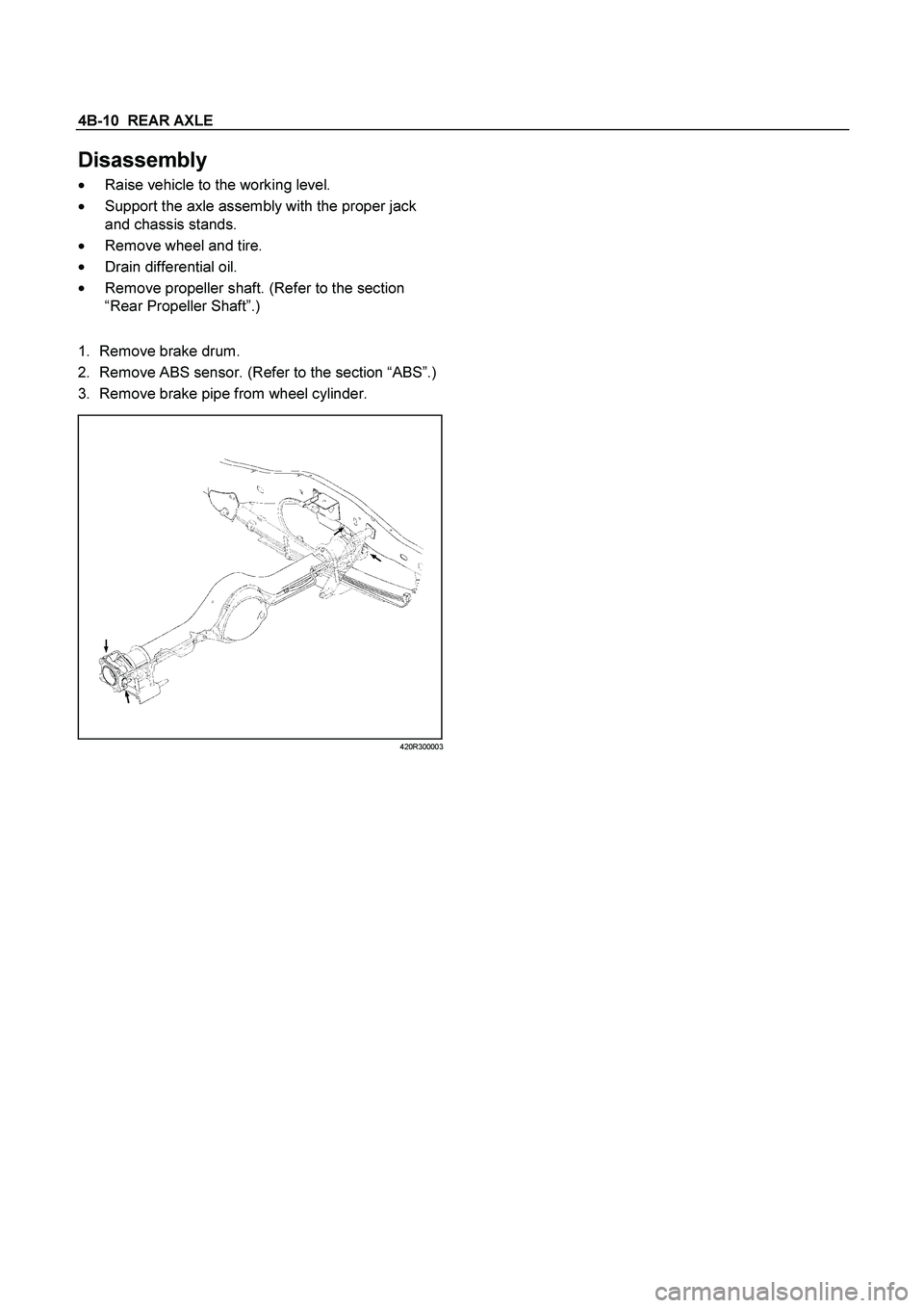
Disassembly
�
Raise vehicle to the working level.
�
Support the axle assembly with the proper jack
and chassis stands.
�
Remove wheel and tire.
�
Drain differential oil.
�
Remove propeller shaft. (Refer to the section
“Rear Propeller Shaft”.)
1.
Remove brake drum.
2. Remove ABS sensor. (Refer to the section “ABS”.)
3. Remove brake pipe from wheel cylinder.
420R300003
Page 182 of 4264
4B-18 REAR AXLE
17.
Install brake pipe and ABS sensor and tighten it to
the specified torque.
Torque :
ABS Sensor
8 N�
m (0.8 kg�
m/69 lb�
ft)
Brake Pipe
16 N�
m (1.6 kg�
m/12 lb�
ft)
420R30003
18.
Bleed brake pipe at the wheel cylinder. (Refer to
the section “Power-assisted Brake System”)
19.
Install brake drum.
�
Install propeller shaft. (Refer to Section “Rear
Propeller Shaft”.)
�
Refill differential oil.
�
Install wheel and tire.
�
Lower vehicle.
Page 207 of 4264
REAR AXLE 4B-43
TROUBLESHOOTING
Refer to this Section to quickly diagnose and repair
rear axle problems.
Each troubleshooting chart has three headings
arranged from left to right.
(1) Checkpoint
(2) Trouble Cause
(3) Countermeasure
This Section is divided into five sub-sections:
1. Abnormal Rear Axle Noise
1) Noise when the engine is driving the vehicle
2) Noise when the vehicle is coasting
3) Intermittent noise
4) Noise when the vehicle is turning
5) Constant noise
2. Vibration
3. Oil Leakage
1) Differential carrier leakage
2) Axle case leakage
3) Axle case to inside hub leakage
4) Axle case to inside brake drum leakage
4. Power Not Being Transmitted to the Wheels
(Propeller Shaft Operation is Normal)
 or a press, install
the needle roller bearing into the yoke so that the snap ring
can be installed in its groove.
CA")
 Sleeve Yoke
(2) Seal
(3) Tube Assembly
1. Discard used seal and install new one.
2. Align the alignment marks and install t")


 Checkpoi")