Page 1232 of 4264
6A – 92 ENGINE MECHANICAL
Oil Seal Installation
Use the special tool to install the front oil seal.
Front Oil Seal Installer: 5-8840-2361-0
1. With the oil seal attached to the sleeve, insert it into the
front end section of the crankshaft.
2. With the oil seal end section attached securely to the
crankshaft, tighten up the center bolt until the sleeve hits
the front end reference plane of the crankshaft securely.
3. Remove the sleeve.
4. With the seal pressed in, check the dimension of the oil
seal section.
Standard Dimension = 1.0 � 0.03mm
NOTE:
Install the oil seal after assembling the timing pulley
housing. The oil seal lip section is applied with oil.
Take notice of the press-in direction of the oil seal.
020R300005
Page 1244 of 4264

6A – 104 ENGINE MECHANICAL
Reassembly
1. Cylinder Body
Use compressed air to thoroughly clean the inside and
outside surfaces of the cylinder body, the oil holes, and the
water jackets.
2. Tappet
1. Apply a coat of engine oil to the tappet and the
cylinder body tappet insert holes.
2. Locate the position mark applied at disassembly (if
the tappet is to be reused).
NOTE:
The tappet must be installed before the camshaft
installation.
3. Crankshaft Upper Bearing
The crankshaft upper bearings have an oil hole and an oil
groove. The lower bearings do not.
1. Carefully wipe any foreign material from the upper
bearing.
NOTE:
Do not apply engine oil to the bearing back faces and
the cylinder body bearing fitting surfaces.
2. Locate the position mark applied at disassembly if the
removed upper bearings are to be reused.
4. Crankshaft
Apply an ample coat of engine oil to the crankshaft journals
and the crankshaft bearing surfaces before installing the
crankshaft.
015R100004015R100003
014LX088
015LX125
Page 1251 of 4264
 setting mark.
5. Align the idler gear set")
ENGINE MECHANICAL 6A – 111
4. Align the idler gear setting mark with the crankshaft
timing gear (1) setting mark.
5. Align the idler gear setting mark with the camshaft
timing gear (2) setting mark.
6. Install the thrust collar and bolts to the cylinder body
through the shaft.
The thrust collar oil hole must be facing up, and the
thrust collar chamfered must be outward.
7. Tighten the idler gear bolt to the specified torque.
Idler Gear "A" Bolt Torque N·m(kg·m/lbft)
30 (3.1/22)
020R300006
22. Idler Gear "B" and Shaft
1. Apply engine oil to the idler gear and the idler gear shaft.
2.
Align the idler gear "B" (3) setting mark with the idler
gear "A" (4) setting mark.
3. Tighten the idler gear bolt to the specified torque.
4. Be sure to remove the lock bolt (5) from idle gear “B”.
Idler Gear "B" Bolt Torque N·m(kg·m/lbft)
76 (7.7/56)
020L200019
5. If the idle gear "B" is disassembled, reassemble in the
following procedure.
1) Drive pins into the main gear, the front gear, and the
rear gear.
020L200007
2) Install the main gear bearing from the front side of
the main gear (the side with the groove).
3) Place the main gear in a vise with copper plate so
that the rear side of the main gear facing up.
020RY00036
Page 1276 of 4264
6A – 136 ENGINE MECHANICAL
RTW36ASH000601
Removal
1. Radiator Grille
� Refer to removal procedure in Sheet Metal section.
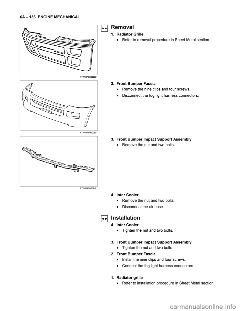
RTW36ASH000501
2. Front Bumper Fascia
� Remove the nine clips and four screws.
� Disconnect the fog light harness connectors.
RTW46ASH002101
3. Front Bumper Impact Support Assembly
� Remove the nut and two bolts.
4. Inter Cooler
� Remove the nut and two bolts.
� Disconnect the air hose.
Installation
4. Inter Cooler
� Tighten the nut and two bolts.
3. Front Bumper Impact Support Assembly
� Tighten the nut and two bolts.
2. Front Bumper Fascia
� Install the nine clips and four screws.
� Connect the fog light harness connectors.
1. Radiator grille
� Refer to installation procedure in Sheet Metal section.
Page 1277 of 4264
ENGINE MECHANICAL 6A – 137
SPECIAL TOOLS
Illustration Tool Number Tool Name
5-8840-0201-0 Filter Wrench
5-8840-0253-0 Filter Wrench
5-8840-2675-0 Compression Gauge
5-8531-7001-0 Adapter; Compression Gauge
5-8840-2723-0 Nozzle Holder Remover
5-8840-0019-0 Sliding Hammer
5-8521-0002-0 Universal Puller
5-8840-2360-0 Oil Seal Remover
9-8523-1423-0 Spring Compressor
9-8523-1212-0 Valve Guide Replacer
Page 1278 of 4264
6A – 138 ENGINE MECHANICAL
Illustration Tool Number Tool Name
5-8840-2040-0 (4JA1L/TC)
5-8840-2313-0 (4JH1TC) Cylinder Liner Installer
5-8840-2038-0 Bearing Replacer; Camshaft
5-8840-2000-0 Pilot Bearing Remover
5-8522-0024-0 Pilot Bearing Installer
5-8840-2033-0 Oil Seal Installer
5-8840-9018-0 Piston Ring Compressor
5-8840-2359-0 Oil Seal Installer
9-8522-0020-0 Crankshaft Timing Gear Installer
5-8840-0266-0 Angle Gauge
5-8840-0214-0 Gear Stopper
5-8840-2039-0 (4JA1L/TC)
5-8840-2304-0 (4JH1TC) Cylinder Liner Remover
Page 1288 of 4264

6B – 8 ENGINE COOLING
Draining and Refilling Cooling System
Before draining the cooling system, inspect the system and
perform any necessary service to ensure that it is clean, does
not leak and is in proper working order. The engine coolan
t
(EC) level should be between the “MIN" and “MAX" lines o
f
reserve tank when the engine is cold. If low, check for leakage
and add EC up to the “MAX" line.
There should not be any excessive deposit of rust or scales
around the radiator cap or radiator filler hole, and the EC
should also be free from oil.
Replace the EC if excessively dirty.
P1010064
1. Completely drain the cooling system by opening the drain
plug at the bottom of the radiator.
2. Remove the radiator cap.
WARNING: To avoid the danger of being burned, do not
remove the cap while the engine and radiator are still hot.
Scalding fluid and steam can be blown out unde
r
pressure.
3. Disconnect all hoses from the EC reserve tank.
Scrub and clean the inside of the reserve tank with soap and water. Flush it well with clean water, then drain it.
Install the reserve tank and hoses.
4. Refill the cooling system with the EC using a solution that is at least 50 percent antifreeze.
Procedure for filling with coolant (in case of full change)
� Make sure that the engine is cool.
� Open radiator cap pour coolant up to filler neck.
� Pour coolant into reservoir tank up to “MAX" line.
� Tighten radiator cap and start the engine. After idling for 2
to 3 minutes, stop the engine and reopen radiator cap. If the
water level is lower, replenish.
WARNING: When the coolant is heated to a high
temperature, be sure not to loosen or remove the radiato
r
cap. Otherwise you might get scalded by not vapor or
boiling water. To open the radiator cap, put a piece of
thick cloth on the cap and loosen the cap slowly to reduce
the pressure when the coolant has become cooler.
Page 1290 of 4264

6B – 10 ENGINE COOLING
WATER PUMP
REMOVAL AND INSTALLATION
Read this Section carefully before performing any removal and installation procedure. This Section gives you
important points as well as the order of operation. Be sure that you understand everything in this Section before you
begin.
Removal
1. Radiator Upper Hose
1) Partially drain the engine coolant.
2) Remove the radiator upper hose.
031R300003
2. Water Outlet Pipe
1) Disconnect the turbocharger-cooling pipe from outlet pipe.
2) Loosen the fixing bolt and remove the water outlet bolt.
3. Thermostat
Remove the thermostat from the thermostat housing.
Take care not to damage the thermostat.
4. Upper Fan Shroud
5. Fan and Fan Clutch 1) Loosen the fan clutch nuts.
2) Remove the fan together with the fan clutch. Take care not to damage the radiator core.
6. Fan Drive Belt and Pulley
1) Loosen the tension adjust bolt on the generator.
2) Remove the fan drive belt with the fan pulley.
030R300001 7. Water Pump
1) Remove the water pump bolts.
2) Remove the water pump.
030R300002


5-8840-2313-0 (4JH1TC) Cylinder Liner Installer
5-8840-2038-0 Bearing Replacer; Camshaft
5-8840-20")