Page 1326 of 4264
6C – 26 FUEL SYSTEM
INJECTION NOZZLE (4JA1L)
DISASSEMBLY
080L200009
Disassembly Steps
1.
Retaining nut 9.
Collar
2.
Nozzle & pin 10.
Spring seat
3.
Spacer & pin 11.
First spring
4.
Lift Piece 12.
Shim (First nozzle opening
pressure adjustment)
5.
Spring seat 13.
Nozzle holder body
6.
Push rod 14.
Eye bolt
7.
Shim (Second nozzle opening
pressure adjustment) 15.
Gasket
8.
Second spring
Important Operations
Injection nozzle adjustment is possible only on the 4JA1L
engine.
The two-spring nozzle holder has been developed to
reduce NOx (Nitrogen Oxides) and particulates from direct
injection diesel engine exhaust.
Before disassembly remove carbon deposit from nozzle
and nozzle holder using a wire brush and wash the outside
nozzle holder assembly.
Caution:
Do not touch nozzle holes with the wire brush during
cleaning it.
Disassemble the nozzle holder assembly to numerical
order.
Page 1345 of 4264

ENGINE ELECTRICAL 6D – 7
GENERATOR
REMOVAL AND INSTALLATION
Read this Section carefully before performing any removal and installation procedure. This Section gives you
important points as well as the order of operation. Be sure that you understand everything in this Section before you
begin.
P1010002
Important Operations-Removal
Cooling Fan Belt
1. Disconnect the battery cables at the battery terminals.
2. Loosen and remove the fan belt adjusting plate bolts.
3. Remove the fan belt from the generator drive pulley.
Generator
1. Remove the vacuum pump hose.
2. Remove the generator bolt and the generator from the bracket.
Important Operations-Installation
Follow the removal procedure in the reverse order to
perform the installation procedure. Pay careful attention to
the important points during the installation procedure.
Generator
1. Install the generator to the bracket.
2. Tighten the generator bolt to the specified torque.
3. Install the vacuum pump hose.
Generator Bolt Torque N �m (kg �m/Ib �ft)
40 (4.1/30)
Page 1348 of 4264
6D – 10 ENGINE ELECTRICAL
RTW46DSH000101
Important Operations
1. Vacuum Pump
1. Loosen the vacuum pump fixing screws.
2. Support the vacuum pump O-ring.
3. Carefully remove the O-ring.
2. Cover
RTW46DSH000201
3. Through Bolt
1. Remove the M5 through bolt.
2. Separate the front and rear sides of the vacuum pump.
3. Insert the tips of 2 ordinary screwdrivers into the space
between the front cover and the stator core. Remove
the front cover and rotor together with the rear cover
and stator.
If removal is difficult, push the rear cover to the side and
lightly tap the end of the shaft with a plastic hammer to
loosen it.
� The front cover oil seal must be replaced with a new
one when the front cover is removed.
� Take care not to damage the stator core with the
screwdriver tips.
RTW46DSH000601
RTW46DSH002101
4. Pulley
1. Carefully clamp the rotor assembly in a vise.
2. Loosen the pulley nut.
3. Remove the pulley and the front cover from the rotor.
Page 1349 of 4264
ENGINE ELECTRICAL 6D – 11
RTW46DSH000301
7. Rotor Assembly
1. Remove the rotor from front cover assembly.
Remove the front cover stator and rectifier.
RTW46DSH000701
8. Front Cover Assembly
1. Remove the front cover bearing retainer screws.
2. Remove the bearing.
RTW46DSH000801
9. Rear rotor bearing
� Re-use improper parts.
10. Rectifier
1. Disconnect the stator coil leads between each rectifier
by melting the solder connection.
Hold the lead wire between the solder and the rectifier
with a pair of long nose pliers.
This will prevent heat transfer and resultant damage to
the rectifier.
RTW46DSH000401
Page 1354 of 4264

6D – 16 ENGINE ELECTRICAL
RTW46DSH000901
Vacuum Pump
Vacuum Pump Disassembly
1. Remove the center plate from the vacuum pump
housing.
2. Remove the vacuum pump rotor and the vanes from
the housing.
Inspection
Vacuum Pump Housing and Center Plate
Inspect the vacuum pump housing and the center plate for
excessive wear, abrasion, and scoring.
If any of these conditions are present, the vacuum pump
housing and center plate must be replaced.
Vane
Inspect the vanes for excessive wear and damage.
Replace all four vanes if either of these conditions are
present.
Never replace only one vane.
Rotor
1. Inspect the rotor for excessive wear, abrasion, and
scoring.
Pay particular attention to the internal spline.
Replace the rotor if any of these conditions are
present.
2. Inspect the generator rotor shaft splines for backlash.
Replace the rotor if backlash is present.
RTW46DSH005201
Check Value
1. Carefully force the valve from the “B” side as shown in
the illustration.
The valve must move smoothly.
If it does not, the check valve must be replaced.
2. Apply compressed air to the “A” side.
Air Pressure kPa (kg/cm
2/psi)
98 - 490 (1-5/14 – 71)
Check for air leakage from the check valve.
If there is air leakage, the valve must be replaced.
Page 1357 of 4264
ENGINE ELECTRICAL 6D – 19
RTW46DSH000401
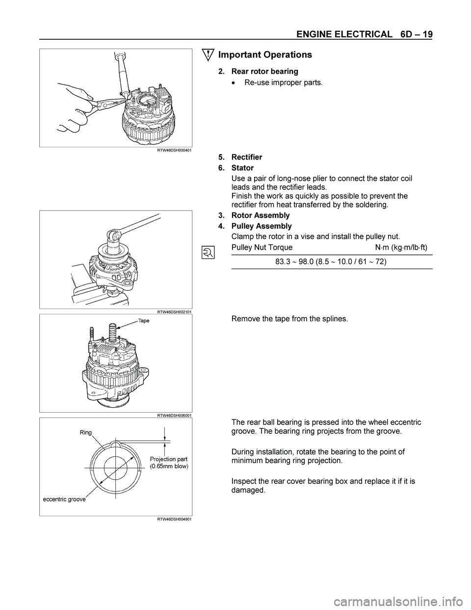
Important Operations
2. Rear rotor bearing
� Re-use improper parts.
5. Rectifier
6. Stator
Use a pair of long-nose plier to connect the stator coil
leads and the rectifier leads.
Finish the work as quickly as possible to prevent the
rectifier from heat transferred by the soldering.
RTW46DSH002101
3. Rotor Assembly
4. Pulley Assembly
Clamp the rotor in a vise and install the pulley nut.
Pulley Nut Torque N�m (kg�m/lb�ft)
83.3 � 98.0 (8.5 � 10.0 / 61 � 72)
RTW46DSH006001
Remove the tape from the splines.
RTW46DSH004901
The rear ball bearing is pressed into the wheel eccentric
groove. The bearing ring projects from the groove.
During installation, rotate the bearing to the point of
minimum bearing ring projection.
Inspect the rear cover bearing box and replace it if it is
damaged.
Page 1358 of 4264
6D – 20 ENGINE ELECTRICAL
RTW46DSH002201
NOTE: Be sure to attach a cooler to B terminal.
RTW46DSH005301
Insert the pin from the outside of the rear cover. Press the
brushes into the brush holder. Complete the assembly
procedure.
Remove the pin after completion of the assembly
procedure.
Page 1360 of 4264

6D – 22 ENGINE ELECTRICAL
STARTER MOTOR
REMOVAL AND INSTALLATION
Read this Section carefully before performing any removal and installation procedure. This Section gives you
important points as well as the order of operation. Be sure that you understand everything in this Section before you
begin.
Important Operations - Removal
Starter Motor
1. Disconnect the battery cable and the ground cable at the battery terminals.
2. Disconnect the magnetic switch cable at the terminal bolts.
3. Disconnect the battery cable at the starter motor and the ground cable at the cylinder body.
4. Remove the starter motor from the engine.
Important Operations – Installation
Follow the removal procedure in the reverse order to
perform the installation procedure. Pay careful attention to
the important points during the installation procedure.
Starter Motor
1. Install the starter motor to the rear plate.
2. Tighten the starter motor bolts to the specified torque.
Starter Motor Bolt Torque N �m (kg �m/lb �ft)
85 (8.7/63)
3. Reconnect the battery cable at the starter motor and
the ground cable at the cylinder body.
4. Reconnect the battery cable and the ground cable at the battery terminals.

DISASSEMBLY
080L200009
Disassembly Steps
1.
Retaining nut 9.
Collar
2.
Nozzle & pi")