Page 666 of 4264
8A-8 ELECTRICAL-BODY AND CHASSIS
3. Use a grommet or guard tube to protect the wiring harness
from contacting a sharp edge or surface.
4. Position the wiring harness with enough clearance from the
other parts and guard the wiring harness with a vinyl tube to
avoid direct contact.
5. The wiring harness between engine and chassis should be
long enough to prevent chafing or damage due to various
vibrations.
Page 670 of 4264

8A-12 ELECTRICAL-BODY AND CHASSIS
ABBREVIATIONS
Abbreviation Meaning of abbreviation Abbreviation Meaning of abbreviation
A Ampere (S) LH Left hand
ABS Anti-lock brake system LWB Long wheel base
ASM Assembly MPI Multipart fuel injection
AC Alternating current M/T Manual transmission
A/C Air conditioner QOS Quick On Start system
ACC Accessories RH Right hand
CARB Carburetor RR Rear
C/B Circuit breaker RWAL Rear wheel anti-lock brake system
CSD Cold start device SRS Supplemental restraint system
DIS Direct ignition system ST Start
EBCM Electronic brake control module STD Standard
ECGI Electronic control gasoline injection SW Switch
ECM Engine control module SWB Short wheel base
ECU Electronic control unit TCM Transmission control module
EFE Early fuel evaporation V Volt
4�2 Two-wheel drive VSV Vacuum switching valve
4�4 Four-wheel drive W Watt (S)
FL Fusible link WOT Wide open throttle
FRT Front W/ With
H/L Headlight W/O Without
IC Integrated circuit
IG Ignition
kW Kilowatt
Page 677 of 4264
ELECTRICAL-BODY AND CHASSIS 8A-19
Battery-1
BATTERY
Inspection
1. Check the battery terminals 1 for corrosion.
2. Check the battery cables
2 for looseness.
3. Check the battery case
3 for cracks and other damage.
4. Check the battery electrolyte level.
Battery-2
Battery Replacement
1. Disconnect the battery ground cable 1.
2. Disconnect the battery positive cable
2.
3. Remove the battery clamp
3.
4. Remove the battery
Caution:
It is important that the battery ground cable be removed
first.
Removing the battery positive cable first can result in a
short circuit.
Jump Starting the Engine with a Booster Battery
The following description assumes that you are using a booster
battery mounted on a second vehicle.
The listed steps (with some minor modifications) are also
applicable if you are using a naked booster battery or special
battery charging equipment.
Page 678 of 4264

8A-20 ELECTRICAL-BODY AND CHASSIS
Caution:
Never push or tow the vehicle in an attempt to start it.
Extensive damage to the emission system and other
vehicle parts will result.
(Only catalytic converter vehicle)
Treat both the discharged battery and the booster battery
with great care when using jumper cables.
Carefully follow the procedure outlined below.
Always be aware of the dangers of sparking.
Failure to follow the following procedure can result in:
a. Serious personal injury, specially to your eyes.
b. Extensive property damage from a battery explosion,
battery acid discharge, or electrical file.
c. Extensive damage to the electronic components o
f
both vehicles.
Do not use a 24 volt booster battery.
Serious damage to the vehicle's electrical system and
electronic components will result.
Jump Starting Procedure
1. Set the parking brake on both vehicles.
2. If one or both vehicles is equipped with a manual
transmission, place the gear shift in the "NEUTRAL"
position.
3. Turn off the ignition on both vehicles.
4. Turn off all vehicle lights and accessories.
5 Be sure that the two vehicles are not touching.
Attach the end of one jumper cable to the booster battery
positive terminal.
6
Attach the other end of the same cable to the discharged
battery positive terminal.
7. Once again, check that the booster battery has a 12 vol
t
rating.
8.
Attach one end of the remaining booster cable to the
booster battery negative terminal.
9.
Attach the other end of the booster cable to a solid ground
(such as the air conditioner compressor mounting bracke
t
or the alternator mounting bracket) in the engine room o
f
the vehicle with the discharged battery.
Be sure that the ground connection is at least 500 mm (20
in) from the discharged battery.
Page 679 of 4264
ELECTRICAL-BODY AND CHASSIS 8A-21
Caution:
Do not attach the booster cable to the discharged battery
negative terminal.
11. Start the engine of the vehicle with the booster battery.
Check that all unnecessary electrical accessories are off.
12. Start the engine of the vehicle with the discharged battery.
13. Remove the jumper cables in the reverse order to which
they were attached.
Caution:
Be absolutely sure to remove the negative jumper cable
from the vehicle with the discharged battery first.
Page 683 of 4264
ELECTRICAL-BODY AND CHASSIS 8A-25
Light Name Rated Power
V-W Number of
Bulbs Lens
Color Remarks
W/O Tacho 5Illumination light 14-2
W/ Tacho 7White
Turn Signal 14-1.12 2 Green
High Beam 14-1.12 1 Blue
Low Fuel 14-1.12 1 Amber
A/T Oil Temp 14-1.12 1 Red
Brake system 14-1.12 1 Red
4WD 14-1.12 1 Green
Seat belt 14-1.12 1 Red
Oil pressure 14-1.12 1 Red
ABS 14-1.12 1 Amber
SEDIMENTER 14-1.12 1 Red
AIR BAG 14-1.12 1 Red
Brake 14-1.12 1 Red
Charge 14-1.12 1 Red
Check Trans 14-1.12 1 Red
Check 4WD 14-1.12 1 Red
Power drive 14-1.12 1 Amber
3rd start 14-1.12 1 Green
4L 14-1.12 1 Green
Cruise Set 14-1.12 1 Green
Check Engine 14-1.12 1 Amber
Front Fog 14-1.12 1 Green
Rear foglight 14-1. 12 1 Amber
Glow 14-1.12 1 Amber
P LED 1 Green
R LED 1 Green
N LED 1 Green
D LED 1 Green
3 LED 1 Green
2 LED 1 Green
Indicator/
Warning
light
A/T shift
indicator
L LED 1 Green
Page 689 of 4264

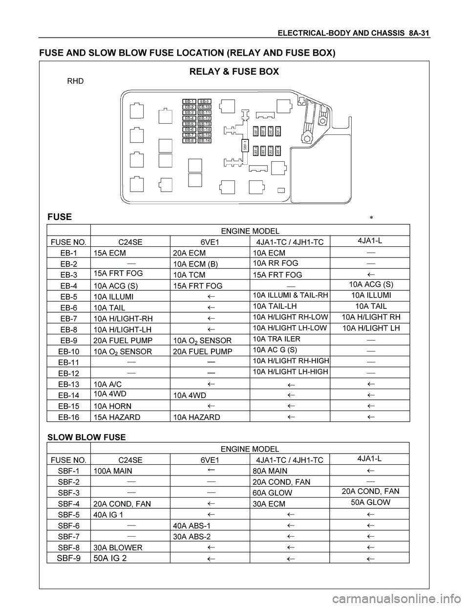
ELECTRICAL-BODY AND CHASSIS 8A-31
FUSE AND SLOW BLOW FUSE LOCATION (RELAY AND FUSE BOX)
RELAY & FUSE BOX
RHD
FUSE �
ENGINE MODEL
FUSE NO. C24SE 6VE1 4JA1-TC / 4JH1-TC4JA1-L
EB-1 15A ECM 20A ECM 10A ECM �
EB-2 �
10A ECM (B) 10A RR FOG �
EB-3 15A FRT FOG
10A TCM 15A FRT FOG �
EB-4 10A ACG (S) 15A FRT FOG � 10A ACG (S)
EB-5 10A ILLUMI � 10A ILLUMI & TAIL-RH10A ILLUMI
EB-6 10A TAIL � 10A TAIL-LH 10A TAIL
EB-7 10A H/LIGHT-RH � 10A H/LIGHT RH-LOW10A H/LIGHT RH
EB-8 10A H/LIGHT-LH � 10A H/LIGHT LH-LOW10A H/LIGHT LH
EB-9 20A FUEL PUMP 10A O2 SENSOR 10A TRA ILER �
EB-10 10A O2 SENSOR 20A FUEL PUMP 10A AC G (S) �
EB-11 � � 10A H/LIGHT RH-HIGH �
EB-12 � � 10A H/LIGHT LH-HIGH�
EB-13 10A A/C �
� �
EB-14 10A 4WD
10A 4WD � �
EB-15 10A HORN � � �
EB-16 15A HAZARD 10A HAZARD � �
SLOW BLOW FUSE
ENGINE MODEL
FUSE NO. C24SE 6VE1 4JA1-TC / 4JH1-TC4JA1-L
SBF-1 100A MAIN �
80A MAIN �
SBF-2 � �
20A COND, FAN �
SBF-3 � �
60A GLOW 20A COND, FAN
SBF-4 20A COND, FAN �
30A ECM 50A GLOW
SBF-5 40A IG 1 � � �
SBF-6 �
40A ABS-1 � �
SBF-7 �
30A ABS-2 � �
SBF-8 30A BLOWER � � �
SBF-9 50A IG 2 � � �
Page 690 of 4264

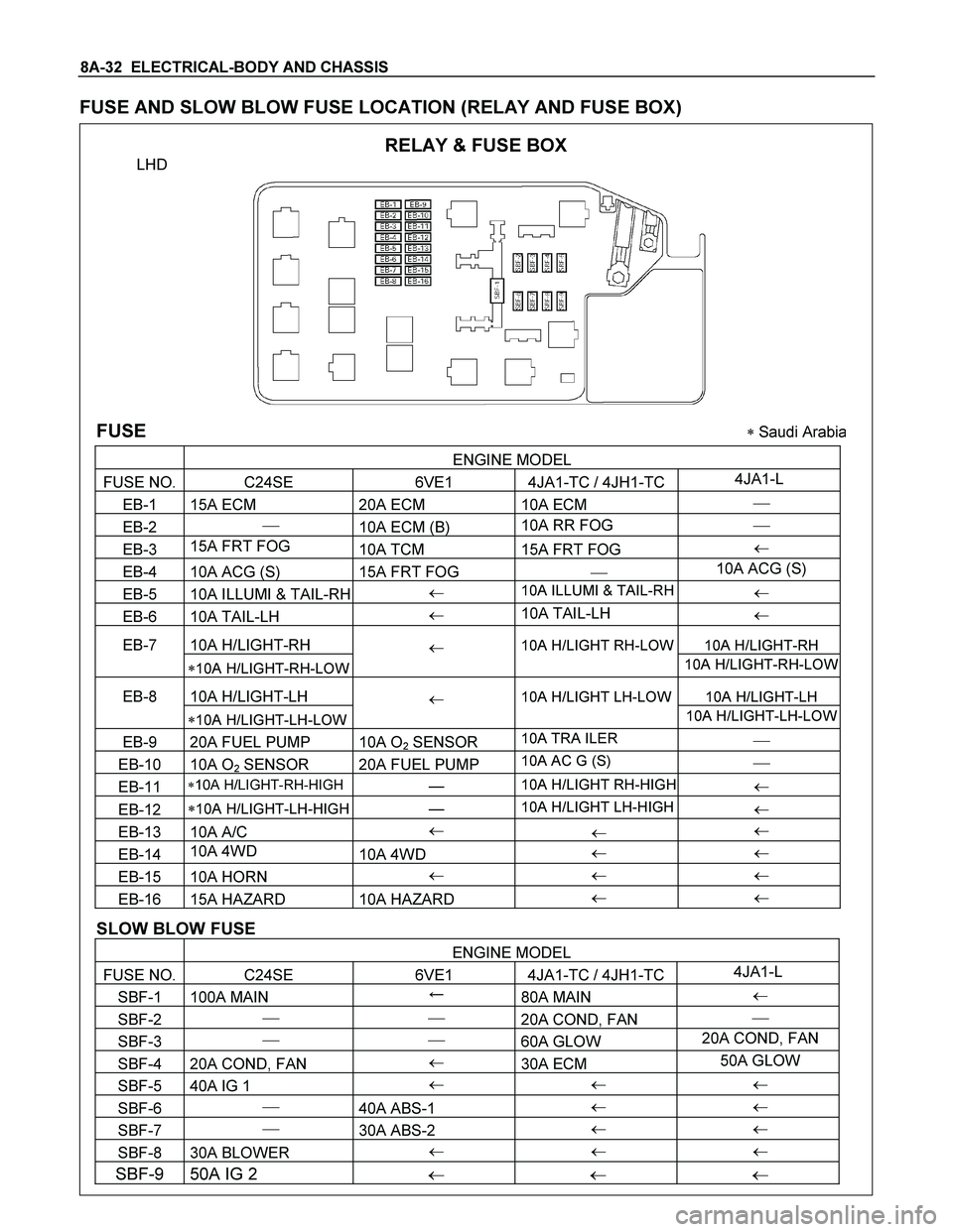
8A-32 ELECTRICAL-BODY AND CHASSIS
FUSE AND SLOW BLOW FUSE LOCATION (RELAY AND FUSE BOX)
RELAY & FUSE BOX
LHD
FUSE � Saudi Arabia
ENGINE MODEL
FUSE NO. C24SE 6VE1 4JA1-TC / 4JH1-TC4JA1-L
EB-1 15A ECM 20A ECM 10A ECM �
EB-2 �
10A ECM (B) 10A RR FOG �
EB-3 15A FRT FOG
10A TCM 15A FRT FOG �
EB-4 10A ACG (S) 15A FRT FOG � 10A ACG (S)
EB-5 10A ILLUMI & TAIL-RH � 10A ILLUMI & TAIL-RH �
EB-6 10A TAIL-LH � 10A TAIL-LH
�
EB-7 10A H/LIGHT-RH 10A H/LIGHT-RH
�10A H/LIGHT-RH-LOW
� 10A H/LIGHT RH-LOW
10A H/LIGHT-RH-LOW
EB-8 10A H/LIGHT-LH 10A H/LIGHT-LH
�10A H/LIGHT-LH-LOW
� 10A H/LIGHT LH-LOW
10A H/LIGHT-LH-LOW
EB-9 20A FUEL PUMP 10A O2 SENSOR 10A TRA ILER �
EB-10 10A O2 SENSOR 20A FUEL PUMP 10A AC G (S) �
EB-11 �10A H/LIGHT-RH-HIGH � 10A H/LIGHT RH-HIGH �
EB-12 �10A H/LIGHT-LH-HIGH � 10A H/LIGHT LH-HIGH �
EB-13 10A A/C �
� �
EB-14 10A 4WD
10A 4WD � �
EB-15 10A HORN � � �
EB-16 15A HAZARD 10A HAZARD � �
SLOW BLOW FUSE
ENGINE MODEL
FUSE NO. C24SE 6VE1 4JA1-TC / 4JH1-TC4JA1-L
SBF-1 100A MAIN �
80A MAIN �
SBF-2 � �
20A COND, FAN �
SBF-3 � �
60A GLOW 20A COND, FAN
SBF-4 20A COND, FAN �
30A ECM 50A GLOW
SBF-5 40A IG 1 � � �
SBF-6 �
40A ABS-1 � �
SBF-7 �
30A ABS-2 � �
SBF-8 30A BLOWER � � �
SBF-9 50A IG 2 � � �