Page 2785 of 4264
 P0650
Malfunction Indicator Lamp (MIL) Control Circuit Malfunction
Step A ction Value(s) Yes No
1 Was the “On-Board Diagnost")
ENGINE DRIVEABILITY AND EMISSIONS 6E–209
Diagnostic Trouble Code (DTC) P0650
Malfunction Indicator Lamp (MIL) Control Circuit Malfunction
Step A ction Value(s) Yes No
1 Was the “On-Board Diagnostic (OBD) System Check”
performed?
—Go to Step 2Go to On Board
Diagnostic
(OBD) System
Check
2 1. Connect the Tech 2.
2. Review and record the failure information.
3. Select “F0: Read DTC Infor By Priority” in “F0:
Diagnostic Trouble Code”.
Is the DTC P0650 stored as “Present Failure”?—Go to Step 3Refer to
Diagnostic Aids
and Go to Step
3
3 1. Using the Tech2, ignition “On” and engine “Off”.
2. Select “Clear DTC Information” with the Tech2 and
clear the DTC information.
3. Operate the vehicle and monitor the “F5: Failed
This Ignition” in “F2: DTC Information”.
Was the DTC P0650 stored in this ignition cycle?—Go to Step 4Refer to
Diagnostic Aids
and Go to Step
4
4 1. Ignition “On”, engine “Off”.
2. Check the “Check Engine” lamp.
Does the lamp turn “On”?—Go to Step 5Go to Step 6
5 1. Ignition “On”, engine “Off”.
2. Check the “Check Engine” lamp.
Does the lamp turn “Off”?—Go to Step 9Go to Step 7
6 Check the “Check Engine” lamp bulb.
If the bulb is burnt out, repair as necessary.
Was the problem found?—Verify repair Go to Step 7
7 Check for poor/faulty connection at the meter
connector and ECM connector. If a poor/faulty
connection is found, repair as necessary.
Was the problem found?
—Verify repair Go to Step 8
32
17
C-56(J2) B-24
Page 3012 of 4264
 ........................................................................................................... 1- 63
Removal and Installation")
1-2 HEATER AND AIR CONDITIONING
PAGE
Duct (Without A/C) ........................................................................................................... 1- 63
Removal and Installation ............................................................................................ 1- 63
Disassembly and Reassembly ................................................................................... 1- 64
Blower Unit Assembly ..................................................................................................... 1- 65
Removal and Installation ............................................................................................ 1- 65
Disassembly and Reassembly ................................................................................... 1- 67
Defroster Nozzle and Vent Duct ..................................................................................... 1- 68
Removal and Installation ............................................................................................ 1- 68
Rear Heater Duct.............................................................................................................. 1- 69
Removal and Installation ............................................................................................ 1- 69
Control Lever Assembly .................................................................................................. 1- 70
Removal and Installation ............................................................................................ 1- 70
Control Panel Illumination Bulb ..................................................................................... 1- 74
Removal and Installation ............................................................................................ 1- 74
Inspection and Repair................................................................................................. 1- 76
Troubleshooting .............................................................................................................. 1- 79
Special Service Tool ........................................................................................................ 1-104
Page 3084 of 4264
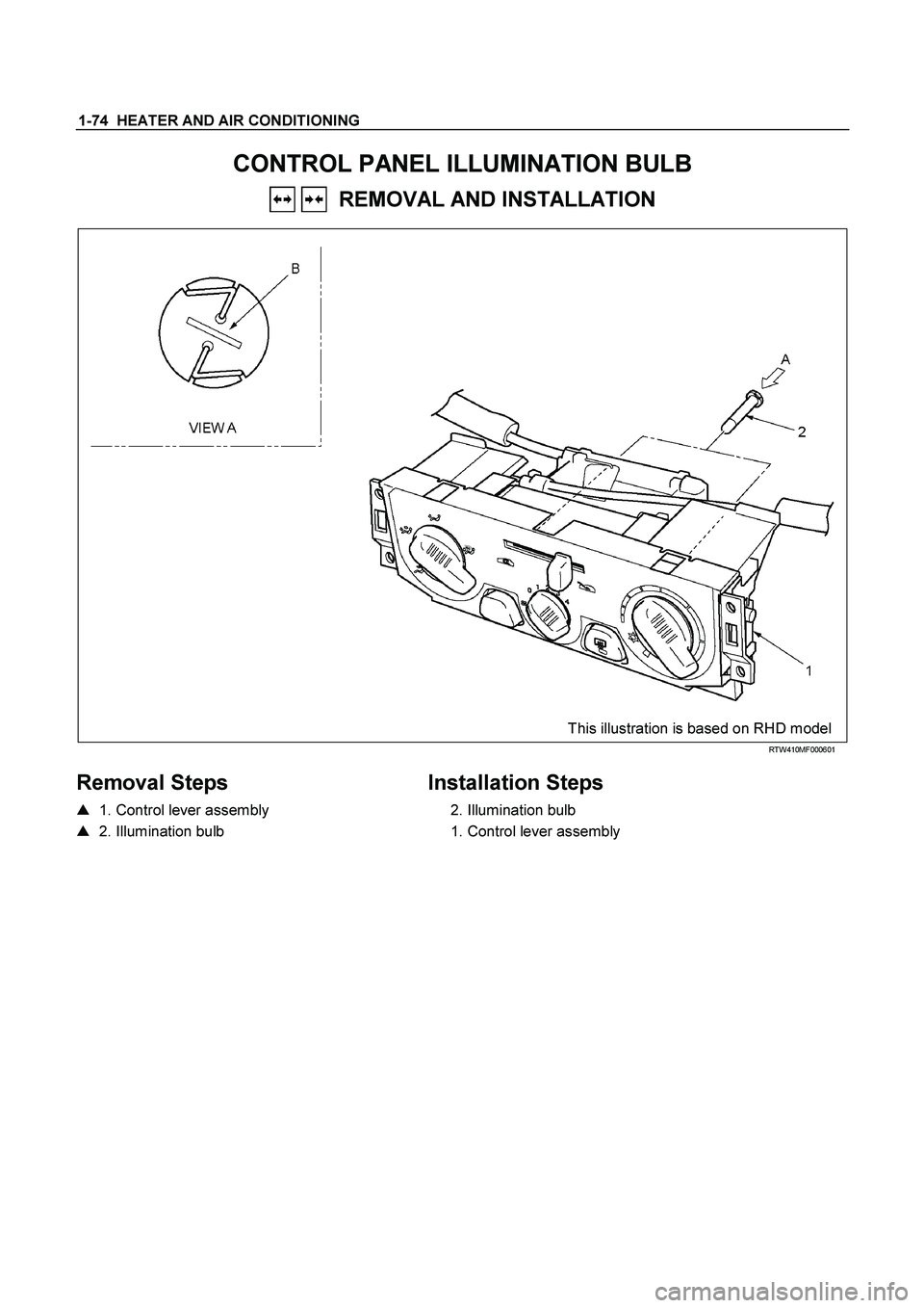
1-74 HEATER AND AIR CONDITIONING
CONTROL PANEL ILLUMINATION BULB
REMOVAL AND INSTALLATION
This illustration is based on RHD model
RTW410MF000601
Removal Steps
� 1. Control lever assembly
� 2. Illumination bulb
Installation Steps
2. Illumination bulb
1. Control lever assembly
Page 3085 of 4264
HEATER AND AIR CONDITIONING 1-75
Important Operation - Removal
1. Control lever assembly
Refer to “CONTROL LEVER ASSEMBLY” in this section.
2. Illumination Bulb
To remove the illumination bulb, insert an ordinary screwdriver
into the slot (B) at the back of the bulb. Turn the bulb
counterclockwise and pull it free.
Page 3322 of 4264
 Yes No
1 Check the meter fuse for the instrument cluster
ignition feed circuit.
Is the fuse normal? �
Go to Step 3")
11A-36 IMMOBILIZER SYSTEM
NO IMMOBILIZER WARNING LAMP
Step Action Value(s) Yes No
1 Check the meter fuse for the instrument cluster
ignition feed circuit.
Is the fuse normal? �
Go to Step 3
Go to Step 2
2 Replace the fuse.
Is the action complete? �
Verify repair
Go to Step 3 �
3 1. Key position is "OFF".
2. Disconnect the meter.
3. Disconnect the engine control module (ECM).
4. Check the circuit between meter and ECM for an
open, short to round, or short to voltage.
Also, check the meter circuit for an open or short to
ground and the DLC ground circuit for an open.
Was a problem found? �
Go to Step 4
Go to Step 5
4 Repair or replace the meter circuit.
Was the action complete? �
Go to Step 5
�
5 1. Key position is "ON," engine "OFF."
2. Observe the check engine lamp.
Is the check engine lamp "ON"? �
Go to Step 6
Go to Step 7
6 Repair or replace the meter.
Was the action complete? �
Go to Step 7 �
7 1. Key position is "OFF".
2. Check the check engine lamp bulb.
Is the check engine lamp bulb normal? �
Go to Step 9
Go to Step 8
8 Replace the check engine lamp bulb.
Is the action complete? �
Verify repair
Go to Step 9 �
9 1. Key position is "OFF".
2. Connect the meter.
3. Connect the engine control module (ECM).
4. Key position is "ON".
5. Observe the check engine lamp.
Note: If a key switch is turned ON, check engine lamp
will turn on and a check engine lamp will be turned off
after a few seconds.
Is the check engine lamp "ON"? �
Verify repair
Go to Step 10
10 Replace the engine control module (ECM).
IMPORTANT: The replacement ICU must be
programmed the immobilizer data by scan tool.
Was the action complete? �
Verify repair �
Page 4129 of 4264
 7A2-137
No. Z2: Mode Lamp (Power Drive or 3rd Start) Does Not Light Up
When The Power Mode or 3rd Start Mode is Turned On
Description:
� The mode lamp on the instrument pane")
DIAGNOSIS (JR405E) 7A2-137
No. Z2: Mode Lamp (Power Drive or 3rd Start) Does Not Light Up
When The Power Mode or 3rd Start Mode is Turned On
Description:
� The mode lamp on the instrument panel does not light up though the power mode or 3rd start mode is turned on
with the ignition switch in ON position.
Possible Cause:
� Faulty mode select switch is considered.
� Bulb burn out.
No. Z3: Mode Lamp (Power Drive or 3rd Start) Lights Up When
The Power Mode or 3rd Start Mode is Turned Off
Description:
� The mode lamp on the instrument panel lights up though the power mode or 3rd start mode is turned off with the
ignition switch in ON position.
Possible Cause:
� Faulty mode select switch is considered.
No. Z4: Oil Temperature Warning Lamp Lights up
Description:
� Sometimes, the oil temperature warning lamp lights up.
Possible Cause:
� When the vehicle is stuck in the mud or continues to accelerate under overload, and ATF temperature exceeds
145 �C, the oil temperature warning lamp lights up.
� If the oil temperature warning lamp lights up under usual service condition, following causes are considered.
� ATF level has increased for some fault.
Refer to "No. Z1: Transmission overheat".
� Lights up due to error of the ATF oil thermo sensor.
No. Z5: Select Lever Feeling is Faulty.
Description:
� Select lever feeling is faulty.
Possible Cause:
� Disordered select cable.
� Disordered select lever.
� Faulty Manual plate.