Page 831 of 4264
ELECTRICAL-BODY AND CHASSIS 8A-173
REMOVAL AND INSTALLATION
REAR COMBINATION LIGHT
Stoplight
Removal
1. Open the rear gate.
2. Remove the screws of rear combination light.
3. Remove the rear combination light assembly.
4. Turn the bulb 2 counterclockwise to remove it.
Installation
Follow the removal procedure in the reverse order to install the
rear combination light.
Pay close attention to the important points mentioned in the
following paragraphs.
Bulb
Be absolutely sure that each bulb is correctly installed.
This will prevent a poor contact and an open circuit.
HIGH MOUNTED STOPLIGHT
Remove the bulb socket
1. Remove the high mounted stoplight ASM.
� Remove the screws.
� Disconnect the connector.
2. Remove the bulb socket.
� Turn the bulb
1 counterclockwise to remove it.
Page 832 of 4264

8A-174 ELECTRICAL-BODY AND CHASSIS
Installation
Follow the removal procedure in the reverse order to install the
rear combination light.
Pay close attention to the important points mentioned in the
following paragraphs.
Bulb
Be absolutely sure that each bulb is correctly installed.
This will prevent a poor contact and an open circuit.
SIDE TURN LIGHT
Removal
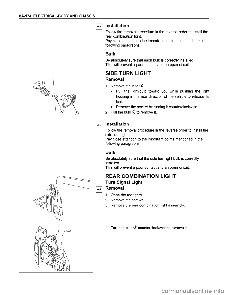
1. Remove the lens 1.
� Pull the light/bulb toward you while pushing the ligh
t
housing in the rear direction of the vehicle to release its
lock.
� Remove the socket by turning it counterclockwise.
2. Pull the bulb
2 to remove it.
Installation
Follow the removal procedure in the reverse order to install the
side turn light.
Pay close attention to the important points mentioned in the
following paragraphs.
Bulb
Be absolutely sure that the side turn light bulb is correctly
installed.
This will prevent a poor contact and an open circuit.
REAR COMBINATION LIGHT
Turn Signal Light
Removal
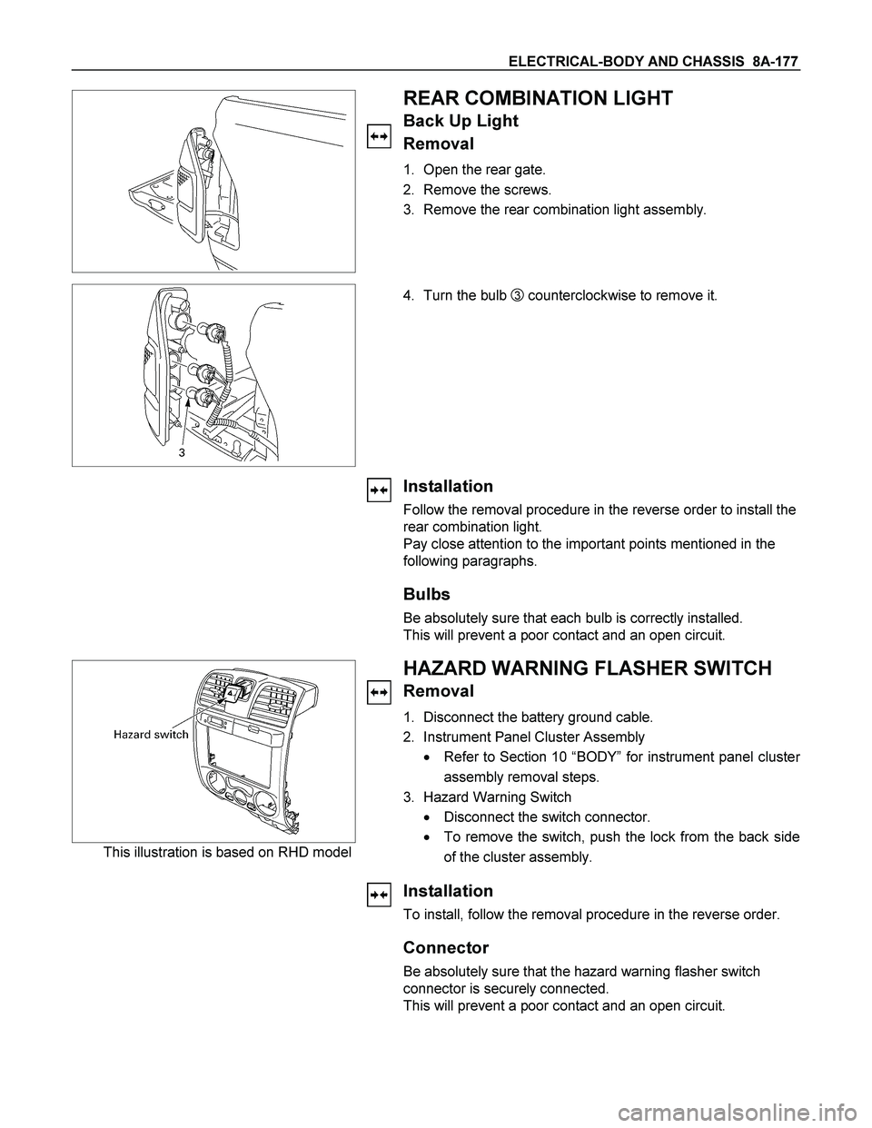
1. Open the rear gate.
2. Remove the screws.
3. Remove the rear combination light assembly.
4. Turn the bulb 1 counterclockwise to remove it.
Page 833 of 4264
ELECTRICAL-BODY AND CHASSIS 8A-175
Installation
Follow the removal procedure in the reverse order to install the
rear combination light.
Pay close attention to the important points mentioned in the
following paragraphs.
Bulb
Be absolutely sure that the rear combination light bulb is
correctly installed.
This will prevent a poor contact and an open circuit.
Page 835 of 4264

ELECTRICAL-BODY AND CHASSIS 8A-177
REAR COMBINATION LIGHT
Back Up Light
Removal
1. Open the rear gate.
2. Remove the screws.
3. Remove the rear combination light assembly.
4. Turn the bulb
3 counterclockwise to remove it.
Installation
Follow the removal procedure in the reverse order to install the
rear combination light.
Pay close attention to the important points mentioned in the
following paragraphs.
Bulbs
Be absolutely sure that each bulb is correctly installed.
This will prevent a poor contact and an open circuit.
This illustration is based on RHD model
HAZARD WARNING FLASHER SWITCH
Removal
1. Disconnect the battery ground cable.
2. Instrument Panel Cluster Assembly
� Refer to Section 10 “BODY” for instrument panel cluste
r
assembly removal steps.
3. Hazard Warning Switch
� Disconnect the switch connector.
� To remove the switch, push the lock from the back side
of the cluster assembly.
Installation
To install, follow the removal procedure in the reverse order.
Connector
Be absolutely sure that the hazard warning flasher switch
connector is securely connected.
This will prevent a poor contact and an open circuit.
Page 849 of 4264
ELECTRICAL-BODY AND CHASSIS 8A-191
TROUBLESHOOTING
1. Dome light dose not light
Checkpoint Trouble Cause Countermeasure
Replace the dome light bulb
Burned out the bulb
NG
Repair or replace the dome
light assembly
Dome light switch function
Switch malfunction
Repair open circuit or
connector contact
Continuity between
connector 5
H-12 - 1 L-1
Open circuit or poor connector
contact
NG NG OK
OK
Dome light bulb continuity
2. Dome light does not go out
Repair or replace the door
switch
Switch malfunction or foreign
material switch
NG
Repair short circuit or
connector contact
Continuity between
connector 2
L-1 -ground
when shutting the door
(Should be no continuity)
Short circuit
NG OK
Door switch function (Both
side)
Page 850 of 4264
8A-192 ELECTRICAL-BODY AND CHASSIS
REMOVAL AND INSTALLATION
DOME LIGHT
Removal
1. Remove the dome light lens 1 free.
2. Remove two dome light fixing screws.
3. Remove the wiring connector.
4. Remove the dome light.
5. Pull the bulb
2 to remove it.
Installation
Follow the removal procedure in the reverse order to install the
dome light.
Pay close attention to the important points mentioned in the
following paragraphs.
Bulb
Be absolutely sure that the dome light bulb is correctly
installed.
This will prevent a poor contact and an open circuit.
Page 852 of 4264

8A-194 ELECTRICAL-BODY AND CHASSIS
Installation
Follow the removal procedure in the reverse order to install the
spot light.
Pay close attention to the important points mentioned in the
following paragraphs.
Connector
Be absolutely sure that the spot light connector is securely
connected.
This will prevent a poor contact and an open circuit.
Bulb
Be absolutely sure that the spot light bulb is correctly installed.
This will prevent a poor contact and an open circuit.
RTW48ASH000801
WARNING BUZZER (ALARMER
CONTROL UNIT)
Removal
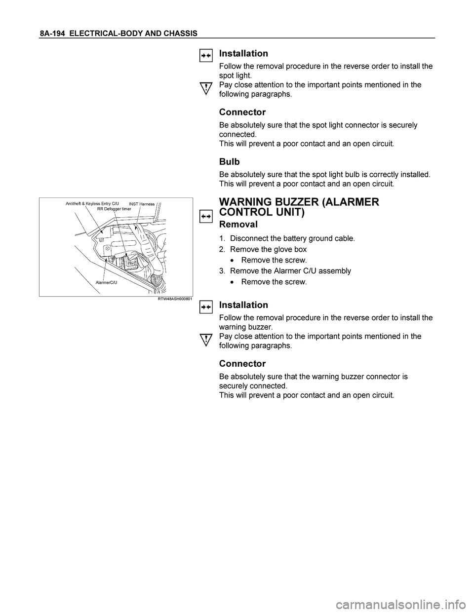
1. Disconnect the battery ground cable.
2. Remove the glove box
� Remove the screw.
3. Remove the Alarmer C/U assembly
� Remove the screw.
Installation
Follow the removal procedure in the reverse order to install the
warning buzzer.
Pay close attention to the important points mentioned in the
following paragraphs.
Connector
Be absolutely sure that the warning buzzer connector is
securely connected.
This will prevent a poor contact and an open circuit.
Page 916 of 4264
8A-258 ELECTRICAL-BODY AND CHASSIS
TEMPERATURE GAUGE AND THERMO UNIT
1. No temperature indicates at all
Checkpoint Trouble Cause Countermeasure
Replace the thermo unit
Thermo unit malfunction
NG
Replace the case baseboard
assy
Gauge function
1. Disconnect the unit
connector then connect
3.4W bulb to wire harness
side with ground
2. Check indicating point
when starter SW. is ON
position (Temperature
should indicate)
Gauge malfunction
Repair open circuit or
connector contact
Continuity between 1 E-19
(C24NE & 6VE1:
E-85 ) and
13
B-24
Open circuit or poor connector
contact
NG NG OK
OK
Thermo unit continuity
between connector
E-19
(C24NE & 6VE1:
E-85 ) and
the ground
2. Temperature gauge incorrect readings in all ranges
Replace the thermo unit
Thermo unit malfunction
NG
Thermo unit resistance
between connector 1
E-19
(C24NE & 6VE1:
E-85 ) and
the ground when
disconnecting the connector
(Specified resistance should
indicate)