Page 917 of 4264
ELECTRICAL-BODY AND CHASSIS 8A-259
FUEL GAUGE AND FUEL TANK UNIT
1. No fuel level indicates at all
Checkpoint Trouble Cause Countermeasure
Replace the tank unit
Open circuit inside the tank
unit
NG Thermo unit malfunction
Replace the case baseboard
assy
Fuel gauge function
1. Disconnect the tank unit
connector then connect
3.4W bulb to wire harness
side
2. Check indicating point
when starter SW. is ON
position (Fuel level should
indicate)
Gauge malfunction
Repair open circuit or
connector contact
Continuity between
connectors 14
B-24 and 3
F-2
Open circuit or poor connector
contact
NG NG OK
OK
Tank unit continuity between
connector 3
F-2 and ground
2. Fuel gauge gives incorrect readings in all ranges
Replace the tank unitTank unit malfunction NG
Tank unit resistance position
with the float at checking
points (Specified resistance
should indicate)
Page 918 of 4264
8A-260 ELECTRICAL-BODY AND CHASSIS
WARNING AND INCIDATOR LIGHT
1. When the parking brake lever is pulled, the indicator light does not light up
Checkpoint Trouble Cause Countermeasure
Replace or reinstall the bulb
Bulb burned out or loose
contact
NG
Adjust or replace the parking
brake SW.
Parking brake SW. installation
position and function
Incorrect SW. adjustment or
poor SW. point contact
Repair open circuit or
connector contact
Continuity between the
parking brake SW. connector
1
C-39 (Lever: 1 R-4) and
9
B-23
Open circuit or poor connector
contact
NG NG OK
OK
Brake indicator light bulb
continuity
Replace the parking brake
SW.
Continuity between the
parking brake SW. connector
1
C-39 (Lever: 1 R-4) and
the ground when the parking
brake is operated
Parking brake SW.
malfunction
NG OK
Page 921 of 4264
ELECTRICAL-BODY AND CHASSIS 8A-263
WARNING LIGHT BULB, INDICATOR
LIGHT BULB AND ILLUMINATION LIGHT
BULB
Removal
Turn the bulb socket counterclockwise and pull the bulb out.
Installation
To Install, follow the removal steps in the reverse order.
FUEL TANK UNIT
Removal
Dismount the fuel tank first, then remove the fuel tank unit.
1. Remove the rear inner liner -LH
� Remove the clip
2. Remove the filler neck.
� Remove the screw
3. Remove the ground with cable.
4. Remove the fuel tank band.
� T/M jack unit on the vehicle.
� Disconnect fuel line quick connectors.
5. Remove the fuel tank unit from the fuel tank.
Page 936 of 4264

8A-278 ELECTRICAL-BODY AND CHASSIS
Low Fuel Indicator Light Inspection
1. Disconnect the fuel tank unit wire connector.
2. Turn the key switch on. Check that the bulb lights.
If operation is not correct, remove and check the bulb or circuit.
or If check whether low fuel turns on fuel input (B-24) at the
time of open and key on.
� meter is check at low fuel
140R300006
Check level sensor operation
1. Remove the fuel tank unit.
2.
Apply battery voltage between terminal (B) and (C) through
a 1.12 watt bulb. Check that the bulb lights.
Note:
It will take a short time for the bulb light.
3. Submerge the sensor in fuel. Check that the bulb goes out.
If operation is not correct, replace the fuel tank unit.
BRAKE SYSTEM WARNING LIGHT
The brake system warning light comes on while the parking
brake is set and the engine run position.
Note:
The parking brake indicator light circuit is designed to
prevent driving of the vehicle with the parking brake on.
It does not indicate the condition of the parking brake
system.
The parking brake switch is in parallel with the brake fluid
switch.
The brake system warning light also comes on when reservoir
brake fluid level falls below the specified limit with the parking
brake released and the engine run position.
Page 1481 of 4264

4JA1/4JH1 ENGINE DRIVEABILITY AND EMISSIONS 6E–109
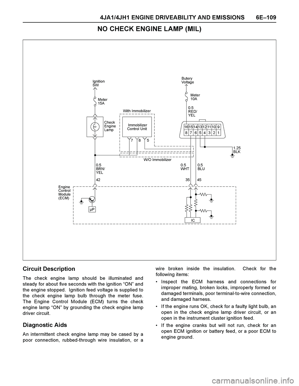
NO CHECK ENGINE LAMP (MIL)
Circuit Description
The check engine lamp should be illuminated and
steady for about five seconds with the ignition “ON” and
the engine stopped. Ignition feed voltage is supplied to
the check engine lamp bulb through the meter fuse.
The Engine Control Module (ECM) turns the check
engine lamp “ON” by grounding the check engine lamp
driver circuit.
Diagnostic Aids
An intermittent check engine lamp may be cased by a
poor connection, rubbed-through wire insulation, or awire broken inside the insulation. Check for the
following items:
Inspect the ECM harness and connections for
improper mating, broken locks, improperly formed or
damaged terminals, poor terminal-to-wire connection,
and damaged harness.
If the engine runs OK, check for a faulty light bulb, an
open in the check engine lamp driver circuit, or an
open in the instrument cluster ignition feed.
If the engine cranks but will not run, check for an
open ECM ignition or battery feed, or a poor ECM to
engine ground.
Page 1482 of 4264

6E–110 4JA1/4JH1 ENGINE DRIVEABILITY AND EMISSIONS
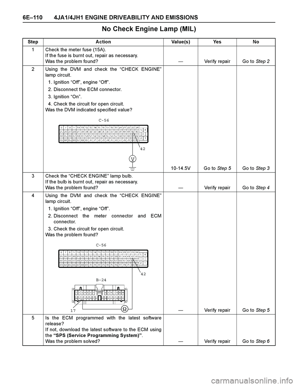
No Check Engine Lamp (MIL)
Step Action Value(s) Yes No
1 Check the meter fuse (15A).
If the fuse is burnt out, repair as necessary.
Was the problem found?—Verify repair Go to Step 2
2 Using the DVM and check the “CHECK ENGINE”
lamp circuit.
1. Ignition “Off”, engine “Off”.
2. Disconnect the ECM connector.
3. Ignition “On”.
4. Check the circuit for open circuit.
Was the DVM indicated specified value?
10-14.5V Go to Step 5Go to Step 3
3 Check the “CHECK ENGINE” lamp bulb.
If the bulb is burnt out, repair as necessary.
Was the problem found?—Verify repair Go to Step 4
4 Using the DVM and check the “CHECK ENGINE”
lamp circuit.
1. Ignition “Off”, engine “Off”.
2. Disconnect the meter connector and ECM
connector.
3. Check the circuit for open circuit.
Was the problem found?
—Verify repair Go to Step 5
5 Is the ECM programmed with the latest software
release?
If not, download the latest software to the ECM using
the “SPS (Service Programming System)”.
Was the problem solved?—Verify repair Go to Step 6
V
42
C-56
42
17
B-24 C-56
Page 1595 of 4264

4JA1/4JH1 ENGINE DRIVEABILITY AND EMISSIONS 6E–223
Rubbed through wire insulation.
Broken wire inside the insulation.
Check for the following conditions:
Poor connection at ECM-Inspect harness connectors
for backed out terminals, improper mating, broken
locks, improperly formed or damaged terminals, andpoor terminal to wire connection.
Damaged harness-Inspect the wiring harness for
damage. If the harness appears to be OK, observe
the DTC P0381 display on the Tech2 while moving
connectors and wiring harnesses. A change in the
display will indicate the location of the fault.
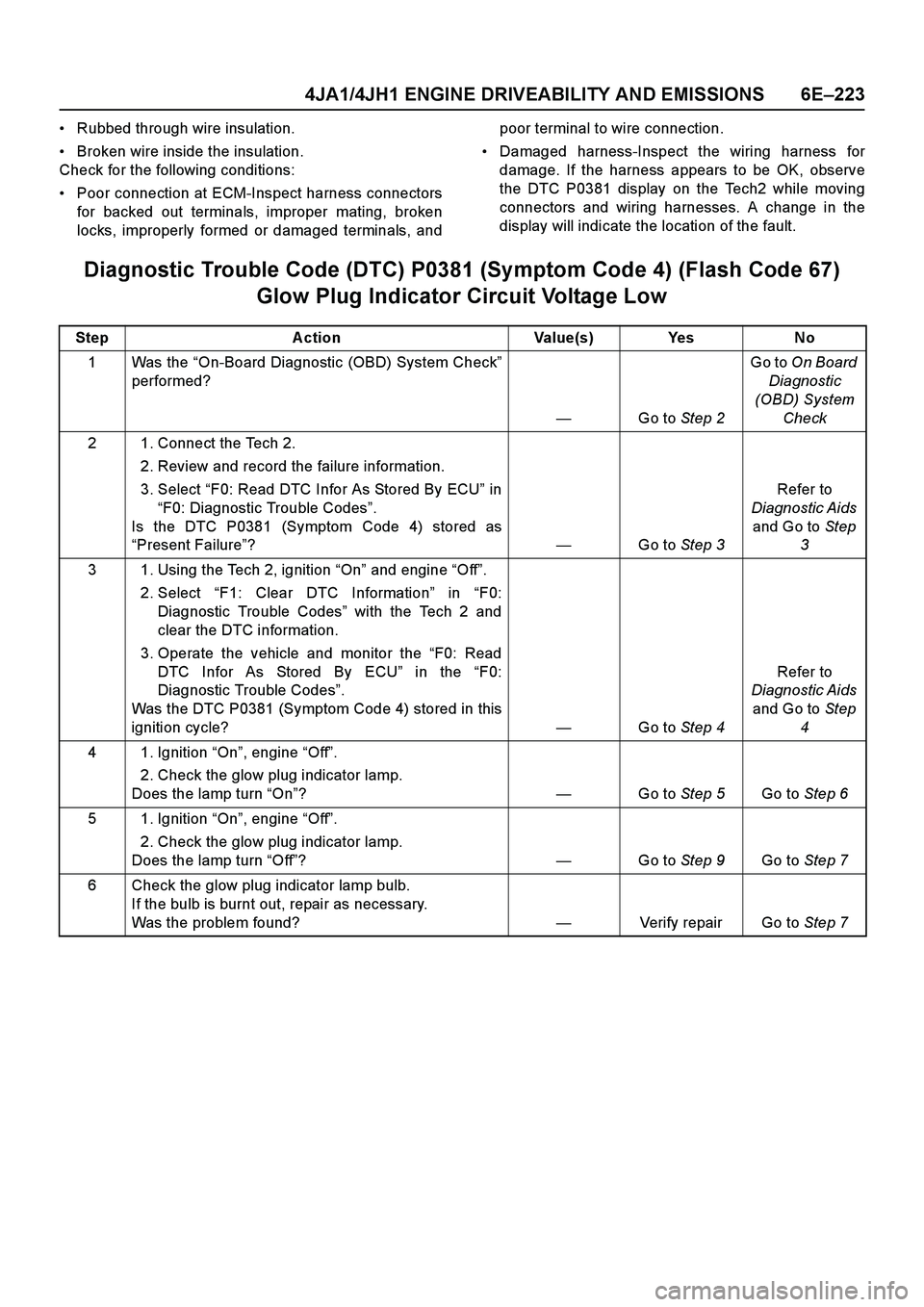
Diagnostic Trouble Code (DTC) P0381 (Symptom Code 4) (Flash Code 67)
Glow Plug Indicator Circuit Voltage Low
Step Action Value(s) Yes No
1Was the “On-Board Diagnostic (OBD) System Check”
performed?
—Go to Step 2Go to On Board
Diagnostic
(OBD) System
Check
2 1. Connect the Tech 2.
2. Review and record the failure information.
3. Select “F0: Read DTC Infor As Stored By ECU” in
“F0: Diagnostic Trouble Codes”.
Is the DTC P0381 (Symptom Code 4) stored as
“Present Failure”?—Go to Step 3Refer to
Diagnostic Aids
and Go to Step
3
3 1. Using the Tech 2, ignition “On” and engine “Off”.
2. Select “F1: Clear DTC Information” in “F0:
Diagnostic Trouble Codes” with the Tech 2 and
clear the DTC information.
3. Operate the vehicle and monitor the “F0: Read
DTC Infor As Stored By ECU” in the “F0:
Diagnostic Trouble Codes”.
Was the DTC P0381 (Symptom Code 4) stored in this
ignition cycle?—Go to Step 4Refer to
Diagnostic Aids
and Go to Step
4
4 1. Ignition “On”, engine “Off”.
2. Check the glow plug indicator lamp.
Does the lamp turn “On”?—Go to Step 5Go to Step 6
5 1. Ignition “On”, engine “Off”.
2. Check the glow plug indicator lamp.
Does the lamp turn “Off”?—Go to Step 9Go to Step 7
6 Check the glow plug indicator lamp bulb.
If the bulb is burnt out, repair as necessary.
Was the problem found?—Verify repair Go to Step 7
Page 1728 of 4264

6E–356 4JA1/4JH1 ENGINE DRIVEABILITY AND EMISSIONS
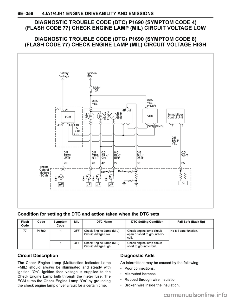
DIAGNOSTIC TROUBLE CODE (DTC) P1690 (SYMPTOM CODE 4)
(FLASH CODE 77) CHECK ENGINE LAMP (MIL) CIRCUIT VOLTAGE LOW
DIAGNOSTIC TROUBLE CODE (DTC) P1690 (SYMPTOM CODE 8)
(FLASH CODE 77) CHECK ENGINE LAMP (MIL) CIRCUIT VOLTAGE HIGH
Condition for setting the DTC and action taken when the DTC sets
Circuit Description
The Check Engine Lamp (Malfunction Indicator Lamp
=MIL) should always be illuminated and steady with
ignition “On”. Ignition feed voltage is supplied to the
Check Engine Lamp bulb through the meter fuse. The
ECM turns the Check Engine Lamp “On” by grounding
the check engine lamp driver circuit for a certain time.
Diagnostic Aids
An intermittent may be caused by the following:
Poor connections.
Misrouted harness.
Rubbed through wire insulation.
Broken wire inside the insulation.
Flash
CodeCode Symptom
CodeMIL DTC Name DTC Setting Condition Fail-Safe (Back Up)
77 P1690 4 OFF Che ck Engine La mp (MIL)
Circuit Voltage LowChe ck engine la mp circuit
open or short to ground cir-
cuit.No fa il-sa fe fun ctio n.
8 OFF Che ck Engine La mp (MIL)
Circuit Voltage HighChe ck engine la mp circuit
sho rt to ground circuit.