Page 3364 of 4264

1=with ALARMER C/U(BUZZER) on")
11B – 18 ANTITHEFT SYSTEM
A
DOOR SW-DR
B-73
DOOR SW-PASSDOOR SW-RR RHDOOR SW-RR LH
L-7
0.5
B/W0.5
B/W0.5
B/W
0.5
R/G0.5
R/G0.5
R/G 0.5
R/G0.5
R/G
1
ALARMER C/U
(BUZZER)
1=with ALARMER C/U(BUZZER) only0.5
R/G0.5
R/G0.5
R/W
1.25
B
1.25
B
2.0
B
2.0
B
DOME
LIGHTHORN;
ANTI THEFT
L-91
H-185 L-9
2
RR DEF
(1)
WELD
SPLICE MAP
LIGHT
C-2
ENGINE �
ROOM RH
R-62
R-61
R-11
R-101
R-91 2
H-26L-11
L-1
2
H-1210
H-127R-1R-10R-9
0.5
R/B0.5
R/B
0.5
R/B0.5
R/B
2 2 2
9
H-2614
H-2613
H-26
C-11 10A
AUDIO
2 B-56 3
B-624 2
B-62 B-62
3 B-63
P-6P-5
8
BIG.1IG.2 MAIN
20
B/Y8
B/R
3
W/B
3
W3
W/B
3
B/Y
0.5
R/Y0.5
R/W0.5
R/W0.85R/Y
1.25
LG/W 5
W
P-11
C-108 2
C-108
B1 B2
IG1 IG2 ACCOFF
ST
P-10P-2SBF-180A (4JA1/4JH1)
100A (6VE1/C24SE)
DOOR LOCKC-14
20A
ANTI THEFTC-17
10A
ROOM LAMPC-16
10A SBF-540A50A
SBF-9
BODY ENGINE
JANCTION BLOCK
B-56
8
B-43
2B-43
6
H-104
H-247
D-207
BD-206H-134
H-257
D-103
D-104B-44
1B-44
2 4
B-445
B-442
C-117
5
H-12 9
B-43 3
B-43B-55
4B-56C-108
4
H-181 C-117
1 6
AUTO DOOR LOCK SW.
DRIVER SIDE
AUTO DOOR LOCK SW.
PASSENGER SIDE
0.5
LG/R
0.5
LG/R0.5
LG/R 0.5
R/L
0.5
R/L0.5
R/L
(POWER WINDOW SW.)
LOCK UN LOCK
WITH POWER WINDOW
DOOR LOCK
MOTORB ACC
ANTI THEFT C/U with SUPER LOCK STARTER
SW.
3
L
POWER
SUPPLY
RTW48AXF025401
WIRING DIAGRAM (Super Lock)
Page 3431 of 4264

POWER-ASSISTED STEERING SYSTEM 3B-1
STEERING
POWER-ASSISTED STEERING SYSTEM
TABLE OF CONTENTS
PAGE
General Description ......................................................................................................... 3B – 4
Power Steering System Test ........................................................................................... 3B – 7
Maintenance ..................................................................................................................... 3B – 8
Fluid Level ........................................................................................................................ 3B – 8
Bleeding The Power Steering System............................................................................ 3B – 8
Bleeding Procedure ......................................................................................................... 3B – 8
Flushing The Power Steering System ............................................................................ 3B – 8
Steering Wheel Free Play Inspection ............................................................................. 3B – 9
Front End Alignment Inspection and Adjustment ......................................................... 3B – 9
Special Tools .................................................................................................................... 3B – 10
Power Steering Unit ......................................................................................................... 3B – 11
Power Steering Unit and Associated Parts ............................................................... 3B – 11
Removal ....................................................................................................................... 3B – 11
Installation ................................................................................................................... 3B – 12
Power Steering Unit Disassembled View .................................................................. 3B – 13
Disassembly ................................................................................................................ 3B – 13
Inspection and Repair ................................................................................................. 3B – 13
Reassembly ................................................................................................................. 3B – 14
Main Data and Specifications ..................................................................................... 3B – 14
Special Tools ............................................................................................................... 3B – 15
Power Steering Pump and Associated Parts (4JH1-TC, 4JA1-TC, 4JA1-L) ............ 3B – 16
Removal ....................................................................................................................... 3B – 16
Installation ................................................................................................................... 3B – 16
Power Steering Pump Disassembled View .............................................................. 3B – 17
Disassembly ................................................................................................................ 3B – 18
Inspection and Repair ................................................................................................. 3B – 18
Reassembly ................................................................................................................. 3B – 19
Main Data and Specifications ..................................................................................... 3B – 19
Page 3446 of 4264
3B-16 POWER-ASSISTED STEERING SYSTEM
Power Steering Pump
Power Steering Pump and Associated Parts (4JH1-TC, 4JA1-TC, 4JA1-L)
442R300002
Legend
(1) Pump Assembly
(2) Hose, Suction
(3) Hose, Flexible
(4) Bolt
Removal
1. Remove the drive belt.
2. Remove the pulley
3. Place a drain pan below the pump.
4. Disconnect the suction hose.
5. Disconnect the flexible hose.
6. Remove the power steering fixing bolt and remove
the pump assembly.
Installation
1. Install the pump assembly to the pump braket,
tighten the fixing bolt to the specified torque.
Torque: 34 - 46 N·m (3.5 – 4.7 kg·m/25 - 34 lb ft)
2. Install the flexible hose.
Tighten the eye bolt to specified torque.
Torque: 49 - 59 N·m (5.0 – 6.0 kg·m/36 - 43 lb ft)
3. Install the pulley and tighten the bolt to the specified
torque.
Torque: 26 - 30 N·m (2.7 –3.1 kg·m/20 - 22 lb ft)
4. Install the drive belt.
5. Connect the suction hose, then fill and bleed system.
Refer to Bleeding the Power Steering System in this
section.
Page 3450 of 4264
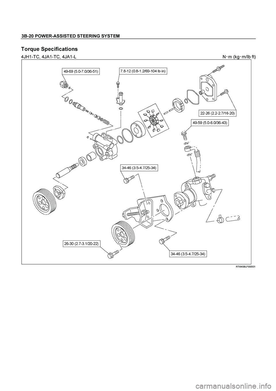
3B-20 POWER-ASSISTED STEERING SYSTEM
Torque Specifications
4JH1-TC, 4JA1-TC, 4JA1-L N�
m (kg�
m/Ib ft)
RTW43BLF000501
Page 3494 of 4264
 MODEL
Front suspension Type Independent wishbone arms, coil spring
with stabilizer bar.
Coil spring")
3C-2 FRONT SUSPENSION
MAIN DATA AND SPECIFICATIONS
4�
�� �2 (EXCEPT HIGH RIDE SUSPENSION) MODEL
Front suspension Type Independent wishbone arms, coil spring
with stabilizer bar.
Coil spring Spring Rate 4JH1-TC / 4JA1-TC / 4JA1-L (ENGINE); 9.62 kg/mm
(94.3 N/mm)
C24SE (ENGINE); 7.94 kg/mm (77.9 N/mm)
Type Gas-sealed. Hydraulic, double acting
Stroke 116.5 mm (4.59 in)
Compressed length 284.0 mm (11.18 in)
Front shock absorber
Extended length 400.5 mm (15.77 in)
Stabilizer bar Diameter 25.0 mm (0.98 in)
4�
�� �2 (HIGH RIDE SUSPENSION) MODEL
Front suspension Type Independent wishbone arms, torsion bar spring
with stabilizer bar.
Length 1142 mm (44.96 in) Torsion bar spring
Diameter 29.0 mm (1.14 in)
Type Gas-sealed. Hydraulic, double acting
Stroke 121.0 mm (4.76 in)
Compressed length 257.0 mm (10.12 in)
Front shock absorber
Extended length 378.0 mm (14.88 in)
Stabilizer bar Diameter 26.0 mm (1.02 in)
4�
�� �4 MODEL
Front suspension Type Independent wishbone arms, torsion bar spring
with stabilizer bar.
Length 1142 mm (44.96 in) Torsion bar spring
Diameter 29.0 mm (1.14 in)
Type Gas-sealed. Hydraulic, double acting
Stroke 121.0 mm (4.76 in)
Compressed length 257.0 mm (10.12 in)
Front shock absorber
Extended length 378.0 mm (14.88 in)
Stabilizer bar Diameter 26.0 mm (1.02 in)
Page 3655 of 4264
TRANSFER CONTROL SYSTEM 7D1-29
CIRCUIT DIAGRAM (4JA1-TC/4JH1-TC)
RTW 48AXF007101
Page 3657 of 4264
TRANSFER CONTROL SYSTEM 7D1-31
CONNECTOR LIST
No. Connector face No. Connector face
B-24
Green
Meter-B C-57
(4JH1-
TC)
ECM
B-54
White
J/B I2 C-67
BlackEHCU
B-62
White
Ignition switch (IGSUB : G1) C-94
(4JH1-
TC)
Gray TCM
B-63
White
Ignition switch (IGSUB : G2) C-95
(6VE1)
WhiteTCM
B-64
Silver
Weld splice 1(Illumination) C-107
WhiteJ/B E2
B-65
Silver
Weld splice 2 (Ground) C-108
WhiteJ/B E1
B-66
White
4WD switch C-109
SilverBody-LH ; ground
C-2
Silver
Engine room-RH ; Ground C-118
(4JH1-
TC)
WhiteA/C Resister & Neutral switch
C-36
Silver
Engine room-LH ; Ground C-119
(6VE1)
BlackAuto cruise actuator
C-56
(4JH1-
TC)
Gray
ECM R-15
BlackTransfer controller
Page 3658 of 4264
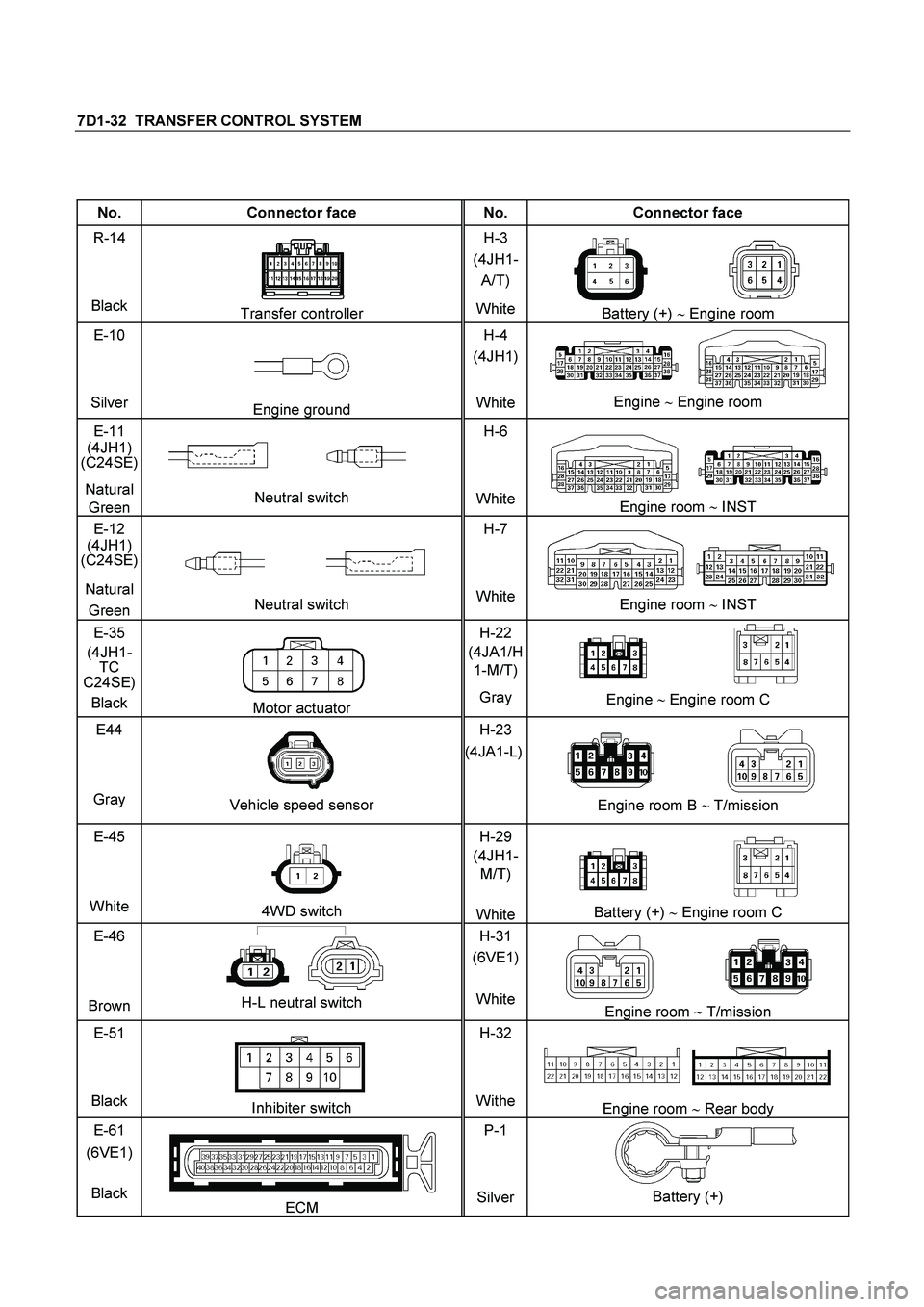
7D1-32 TRANSFER CONTROL SYSTEM
No. Connector face No. Connector face
R-14
Black
Transfer controller H-3
(4JH1-
A/T)
WhiteBattery (+) � Engine room
E-10
Silver
Engine ground H-4
(4JH1)
WhiteEngine � Engine room
E-11
(4JH1)
(C24SE)
Natural
Green
Neutral switch H-6
White
Engine room �
INST
E-12
(4JH1)
(C24SE)
Natural
Green
Neutral switch H-7
WhiteEngine room �
INST
E-35
(4JH1-
TC
C24SE)
Black
Motor actuator H-22
(4JA1/H
1-M/T)
Gray Engine �
Engine room C
E44
Gray
Vehicle speed sensor H-23
(4JA1-L)
Engine room B �
T/mission
E-45
White
4WD switch H-29
(4JH1-
M/T)
WhiteBattery (+) � Engine room C
E-46
Brown
H-L neutral switch H-31
(6VE1)
WhiteEngine room �
T/mission
E-51
Black
Inhibiter switch H-32
WitheEngine room � Rear body
E-61
(6VE1)
Black
ECM P-1
SilverBattery (+)

442R300002
Legend
(1) Pump Assembly
(2) Hose, Suction
(3) Hose,")

RTW 48AXF007101")

ECM
B-54
White
J/B I2 C-67
BlackEHCU
B-62
White
Ignition switch")