Page 3047 of 4264
HEATER AND AIR CONDITIONING 1-37
REMOVAL AND INSTALLATION (EXCEPT 4JA1-TC, 4JH1-TC)
RTW410LF000701
Removal Steps
1. Radiator grille
2. Engine hood lock
3. Engine hood front end stay
4. Pressure switch connector
5. Condenser fan connector
6. Refrigerant line
7. Refrigerant line
8. Receiver/drier bracket
9. Receiver/drier
10. Condenser assembly
Installation Steps
10. Condenser assembly
9. Receiver/drier
8. Receiver/drier bracket
7. Refrigerant line
6. Refrigerant line
5. Condenser fan connector
4. Pressure switch connector
3. Engine hood front end stay
2. Engine hood lock
1. Radiator grille
Page 3099 of 4264
HEATER AND AIR CONDITIONING 1-89
4JH1 – TC
RTW410LF000101
Page 3100 of 4264
1-90 HEATER AND AIR CONDITIONING
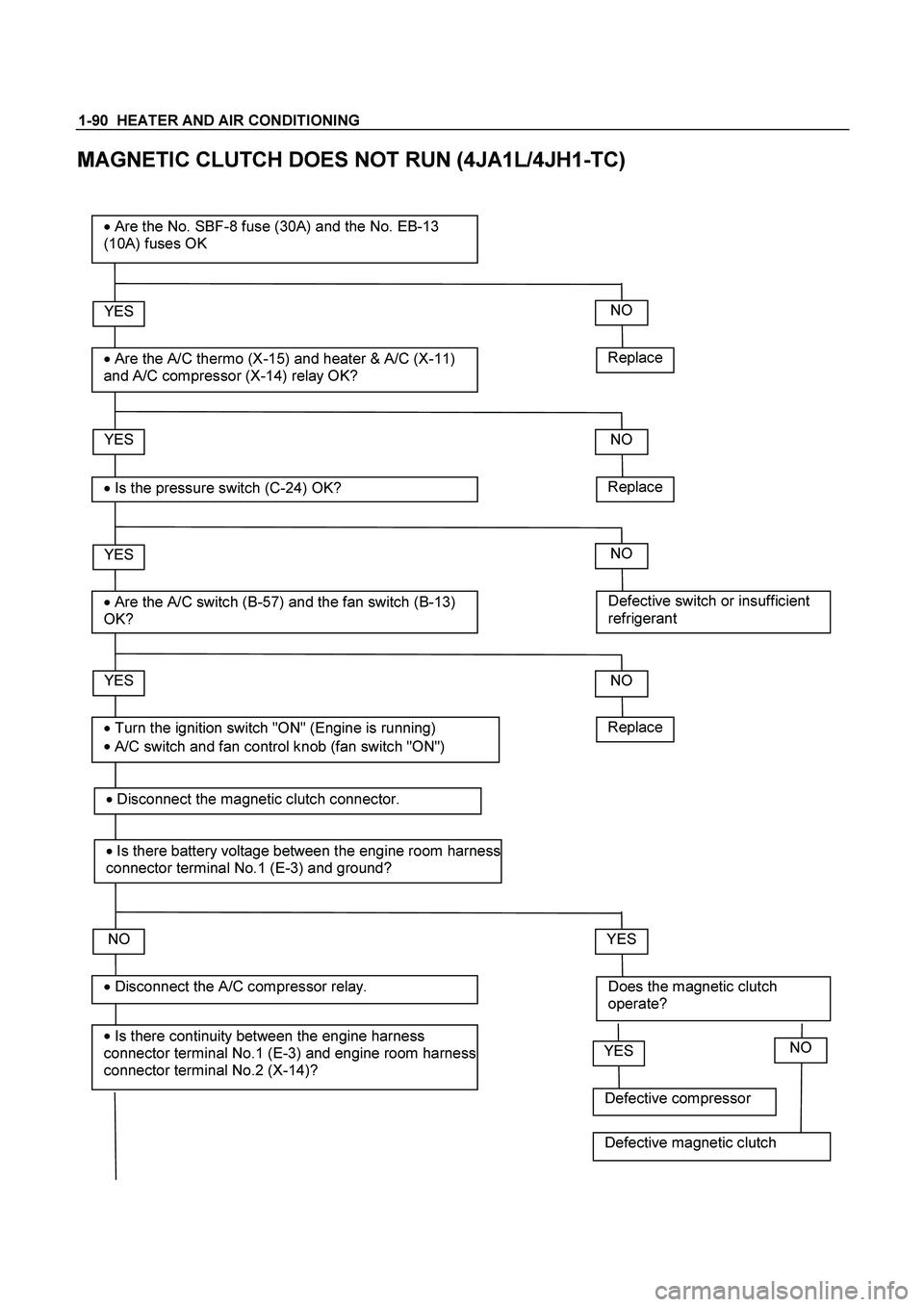
MAGNETIC CLUTCH DOES NOT RUN (4JA1L/4JH1-TC)
Replace
YES
�
Are the A/C thermo (X-15) and heater & A/C (X-11)
and A/C compressor (X-14) relay OK?
� Are the No. SBF-8 fuse (30A) and the No. EB-13
(10A) fuses OK
YES
�
Is the pressure switch (C-24) OK?
YES
�
Are the A/C switch (B-57) and the fan switch (B-13)
OK?
NO
YES
�
Is there continuity between the engine harness
connector terminal No.1 (E-3) and engine room harness
connector terminal No.2 (X-14)?
� Disconnect the A/C compressor relay.
� Turn the ignition switch "ON" (Engine is running)
�
A/C switch and fan control knob (fan switch "ON")
NO
Replace
NO
Defective switch or insufficient
refrigerant
NO
NO
Does the magnetic clutch
operate?
YES
Replace
�
Disconnect the magnetic clutch connector.
� Is there battery voltage between the engine room harness
connector terminal No.1 (E-3) and ground?
Defective compressor
YESNO
Defective magnetic clutch
Page 3102 of 4264

1-92 HEATER AND AIR CONDITIONING
YES
� Disconnect the condenser fan relay connector
condenser fan.
YES
�
Is there battery voltage between the engine
room harness connector terminal NO.3 (C-
24) and ground? Open circuit between the condenser
fan relay 4JH1TC No.4 (X-6) 4JA1L
No. 3 (X-13) and engine room harness
connector terminal No. 4 (X-14).
NO
� Is there continuity between the relay terminal
4JH1TC No. 4 (X-6) 4JA1L No.3 (X-13)and
engine room harness connector terminal No.4
(C-24)?
YES
�
connect the A/C thermo relay connector.
Open circuit between the No. EB-13
fuse and engine room harness
connector terminal No. 3 (C-24).
NO
YES
�
Is there battery voltage between the engine
room harness connector terminal No.3 (C-55)
dd?
Open circuit between the engine room
harness connector terminal No. 2 (C-
55) and the engine room harness
connector terminal No. 2 (C-24).
NO
YES
�
Is there continuity between the engine room
harness connector terminal No.1 (C-55) and
ground (C-109) ? or (cooler only) the short
connector terminal No.3 (B-79) and ground (C-
109
)?
Open circuit between the No. EB-13
fuse and engine room harness
connector terminal No. 3 (C-55).
NO
�
Disconnect the electronic themostat.
�
Is there continuity between the engine room
harness connector terminal No. 2 (C-55) and the
engine room harness connector terminal No. 2
(C-24).
Open circuit between and engine room
harness connector terminal No. 3 (X-
15) and the engine room harness
connector terminal No. 1(C-24).
NO
Page 3240 of 4264
7B1-76 MANUAL TRANSMISSION
Transmission Case
Major Component
RTW47BLF000101
Legend
(1) Gear Control Box Assembly and Gasket (8) Front Cover (with Oil Seal)
(2) Rear Case Assembly (9) Top Gear Bearing Snap Ring
(3) Intermediate Plate with Gear Assembly (10) Release Bearing : C24NE
(4) Transmission Case (11) Shift Fork : C24NE
(5) Release Bearing (with Spring): 4JH1-TC (12) Fulcrum Bridge : 6VE1
(6) Shift Fork: 4JH1-TC (13) Release Bearing : 6VE1
(7) Counter Front Bearing Snap Ring (14) Shift Fork : 6VE1
Page 3287 of 4264

IMMOBILIZER SYSTEM 11A-1
SECTION 11A
IMMOBILIZER SYSTEM
CONTENTS
Service Precaution.................................................
11A-2
General Description...............................................
11A-3
What happens without proper transponder
operation? ..........................................................
11A-6
No proper transponder is available, what
should be done for the system? ......................
11A-6
Caution to the operation.....................................
11A-6
Summary of operation........................................
11A-6
What your organization should provide for
your customer ....................................................
11A-6
Car Pass .............................................................
11A-6
Security code management ..............................
11A-6
Essential tool (Scan tool : Tech-2) ..................
11A-6
Circuit Diagram .................................................
11A-7
Parts Location.........................................................
11A-10
Immobilizer control unit (ICU); For Electronic
Control Engine (6VE1, C24SE, 4JH1-TC,
4JA1-TC) .......................................................... 11A-11
Pin-outs; For Electronic Control Engine
(6VE1, C24SE, 4JH1-TC, 4JA1-TC)...............
11A-12
Immobilizer control unit (ICU); Mechanical
Control Engine (4JA1-T) .................................. 11A-13
Immobilizer coil (Antenna) ...................................
11A-15
Transponder (Key) ............................................ 11A-15
Immobilizer warning lamp ................................. 11A-15
Engine control module (ECM) .......................... 11A-15
Car Pass Card .................................................. 11A-16
Loss of car pass card.........................................
11A-16
Instructions on Filling Out the form "Data
request, car pass" .............................................
11A-16
Important Instructions ........................................
11A-17
lmportant information on Programming .............
11A-19
Security code ......................................................
11A-19
Entering a code ..................................................
11A-19
Transponder (Key) .............................................
11A-19
Important .............................................................
11A-19
Tech-2 Scan Tool ..................................................
11A-20
Tech-2 Features .................................................
11A-21
Getting Started ...................................................
11A-21
Operating Procedure .........................................
11A-22
Menu ....................................................................
11A-23
DTC ......................................................................
11A-23
Clear DTC Information .......................................
11A-23
Tech-2 Data Display ...........................................
11A-23
Check Vehicle Identification Number (VIN) ....
11A-23
Reset Immobilizer (Reset Immobilizer
Control Unit) .......................................................
11A-23
Reset Engine Control Module (Reset ECM) ...
11A-24
Erase transponder key .......................................
11A-24
Programming Immobilizer Function .................
11A-25
Programming ICU ...............................................
11A-26
Programming ECM .............................................
11A-27
Programming ICU and ECM .............................
11A-28
Transponder program ........................................
11A-28
Data List ...............................................................
11A-30
Diagnostic procedure ............................................
11A-31
Clearing Diagnostic Trouble Codes ....................
11A-31
Verifying Vehicle Repair ........................................
11A-31
Diagnostic Aids ......................................................
11A-31
Check the condition for system parts ..............
11A-31
Check the Electro-Magnetic Interference
(EMI) ....................................................................
11A-31
Check the other items ........................................
11A-31
Check the operation ...........................................
11A-31
Diagnostic Trouble Code (DTC) list ....................
11A-32
IMMOBILIZER SYSTEM CHECK ........................
11A-33
NO IMMOBILIZER WARNING LAMP .................
11A-36
IMMOBILIZER WARNING LAMP ON STEADY 11A-37
B0001 REPLACE ELECTRONIC CONTROL
UNIT (ECU) (IMMOBILIZER FAULT) ................
11A-38
B0002 IMMOBILIZER NOT PROGRAMMED ....
11A-39
B0003 TRANSPONDER KEY PROBLEM ..........
11A-40
B0004 IMMOBILIZER COIL CIRCUIT
(ANTENNA COIL FAULT) ...................................
11A-42
B0005 COMMUNICATION LINE W VOLTAGE
LOW .......................................................................
11A-43
B0006 COMMUNICATION LINE W VOLTAGE
HIGH .......................................................................
11A-44
B0007 NO ENGINE REQUEST RECEIVED ......
11A-45
B0008 WRONG TRANSPONDER KEY .............
11A-47
B0009 NO TRANSPONDER KEY
PROGRAMMED ...................................................
11A-48
Page 3290 of 4264
11A-4 IMMOBILIZER SYSTEM
Diesel Engine With ECM (4JH1-TC/4JA1-TC)
LTW3BALF000201
Page 3294 of 4264
11A-8 IMMOBILIZER SYSTEM
Diesel Engine With ECM (4JH1-TC/4JA1-TC)
RTW4B0LF000101

RTW410LF000701
Removal Steps
1. Radiator grille
2. Engine hood lock
3. Engine hood fron")

 Gear Control Box Assembly and Gasket (8) Front Cover (with Oil Seal)
(2) Rear Case Assemb")

LTW3BALF000201")

RTW4B0LF000101")