Page 3297 of 4264
IMMOBILIZER SYSTEM 11A-11
Immobilizer control unit (ICU); For
Electronic Control Engine (6VE1,
C24SE, 4JH1-TC, 4JA1-TC)
Immobilizer control unit (ICU) permits engine starting,
when the security code which compares the securit
y
code registered into the transponder (key) and the
security code registered into ICU, and is similarl
y
registered into ICU and engine control unit (ECM) is
compared and it is judged that it is normal. When the
code registered into the key is unusual, and when not
recognizing a security code, ICU does not permit
starting of engine.
RUW38HSF000101
Page 3298 of 4264
11A-12 IMMOBILIZER SYSTEM
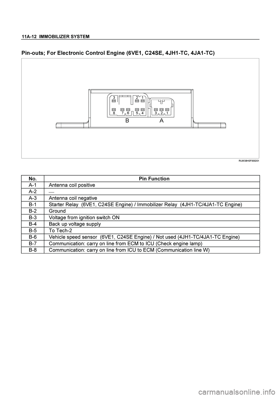
Pin-outs; For Electronic Control Engine (6VE1, C24SE, 4JH1-TC, 4JA1-TC)
RUW38HSF000201
No. Pin Function
A-1 Antenna coil positive
A-2
�
A-3 Antenna coil negative
B-1 Starter Relay (6VE1, C24SE Engine) / Immobilizer Relay (4JH1-TC/4JA1-TC Engine)
B-2 Ground
B-3 Voltage from ignition switch ON
B-4 Back up voltage supply
B-5 To Tech-2
B-6 Vehicle speed sensor (6VE1, C24SE Engine) / Not used (4JH1-TC/4JA1-TC Engine)
B-7 Communication: carry on line from ECM to ICU (Check engine lamp)
B-8 Communication: carry on line from ICU to ECM (Communication line W)
Page 3301 of 4264
IMMOBILIZER SYSTEM 11A-15
Immobilizer coil (Antenna)
Immobilizer coil is install in order that ICU may check
the security code memorized by the transponder (key).
RUW38HSH000301
Transponder (Key)
Transponder is installed in the inside of a key.
Transponder has memorized the security code of a
immobilizer system.
LTW3BASH000101
Legend
(1) Transponder (Key)
Check engine lamp
Check engine lamp displays failure or a system
operation of a immobilizer system by flash of a lamp.
LTW3BASH000201
Engine control module (ECM)
ECM will stop engine, if it communicates with ICU and
abnormalities are detected by a key and the immobilize
r
system.
LTW3BASH000301
Legend
(1) ECM (6VE1 engine)
(2) ECM (C24SE engine)
(3) ECM (4JH1-TC engine)
Page 3318 of 4264
 list with ECM
�
�� � Immobilizer Control Unit (ICU)
DTC
Description Note
B0001
REPLACE ELECTRONIC CONTROL UNIT
(ECU) (IMMOBILIZER FAULT")
11A-32 IMMOBILIZER SYSTEM
Diagnostic Trouble Code (DTC) list with ECM
�
�� � Immobilizer Control Unit (ICU)
DTC
Description Note
B0001
REPLACE ELECTRONIC CONTROL UNIT
(ECU) (IMMOBILIZER FAULT) This error code appears if a RAM /ROM Error was
detected or the EEPROM is defect.
B0002 IMMOBILIZER NOT PROGRAMMED Immobilizer control unit is not programmed.
B0003 TRANSPONDER KEY PROBLEM �
Reading of Transponder information failed with ignition
on transponder has a fault.
�
Hardware fault in reading circuit.
B0004
IMMOBILIZER COIL CIRCUIT (ANTENNA
COIL FAULT) Immobilizer coil has a fault.
B0005 COMMUNICATION LINE W VOLTAGE LOW Short circuit to ground or open circuit.
B0006 COMMUNICATION LINE W VOLTAGE HIGH Short circuit to 12V.
B0007 NO ENGINE REQUEST RECEIVED No ECM Challenge.
B0008 WRONG TRANSPONDER KEY Incorrect security code response received.
B0009 NO TRANSPONDER KEY PROGRAMMED Transponder security code table empty
B0010 UNKNOWN TRANSPONDER KEY Transponder security code not valid.
�
�� � Engine Control Module (ECM: Gasoline Engine {6VE1, C24SE})
DTC Description
Note
P1626 No Response From Immobilizer Refer to Engine Control system section
P1631 Received Response Was Not Correct Refer to Engine Control system section
P1648 Received Incorrect Security Code Refer to Engine Control system section
P1649 Security Code & Security Key Not
Programmed Refer to Engine Control system section
�
�� � Engine Control Module (ECM: Diesel Engine {4JH1-TC, 4JA1-TC})
DTC Description Note
P1610 Seeds and Key File Destroyed Refer to Engine Control system section
P1611 Wrong Security Code Entered Refer to Engine Control system section
P1612/
P1613 Immobilizer No or Wrong Signal Refer to Engine Control system section
P1649 Wrong Transponder Key Refer to Engine Control system section
Page 3331 of 4264
 Yes No
1
Was the \"Immobilizer System Check\" performed? �
Go to Step 2
Go to Immobilizer
System Check
2 Recheck")
IMMOBILIZER SYSTEM 11A-45
B0007 NO ENGINE REQUEST RECEIVED
Step Action Value(s) Yes No
1
Was the "Immobilizer System Check" performed? �
Go to Step 2
Go to Immobilizer
System Check
2 Recheck the DTC on ICU.
1. Key position is “OFF”.
2. Install the scan tool on vehicle.
3. Key position is “ON”.
4. Check the DTC on scan tool.
Is DTC B0007 stored? �
Go to Step 3
Refer to
Diagnostic Aids
3 Check the immobilizer communication line circuit.
1. Key position is “OFF”.
2. Disconnect the immobilizer control unit (ICU).
3. Disconnect the engine control module (ECM).
4. Check the immobilizer communication line circuit
for an open, short to ground, or short to voltage.
Also, check the ICU and ECM ignition feed circuits for
an open or short to ground and the ICU and ECM
ground circuit for an open.
Was a problem found? �
Go to Step 4
Go to Step 5
4 Repair or replace the immobilizer communication line
circuit.
Was the action complete? �
Verify repair �
5 Recheck the DTC on ICU.
1. Key position is “OFF” and keep the position for
more than 30 seconds.
2. Key position is “ON”.
3. Check the DTC on scan tool.
Is DTC B0007 stored? �
Go to Step 6
Verify repair
6 Recheck the DTC on ECM.
1. Key position is “OFF” and keep the position for
more than 30 seconds.
2. Key position is “ON”.
3. Check the DTC on scan tool.
Are below DTCs stored?
P1649 (6VE1, C24SE) , P1611/P1614 (4JH1-TC) �
Go to Step 7
Go to Step 9
7 Perform the immobilizer programming functions.
(Refer to "Important information on Programming")
�
Engine control module (ECM).
Was the action complete? �
Go to Step 8
Go to Step 11
8 Recheck the DTC on ECM.
1. Key position is “OFF” and keep the position for
more than 30 seconds.
2. Key position is “ON”.
3. Check the DTC on scan tool.
Are below DTCs stored?
P1649 (6VE1, C24SE) , P1611/P1614 (4JH1-TC) �
Go to Step 11
Go to Step 12
Page 3332 of 4264
 Yes No
9 Check the immobilizer programming functions.
� Engine control module (ECM).
If a problem is found, repair as necessary.
(Refer to \"Impor")
11A-46 IMMOBILIZER SYSTEM
Step Action Value(s) Yes No
9 Check the immobilizer programming functions.
� Engine control module (ECM).
If a problem is found, repair as necessary.
(Refer to "Important information on Programming")
Was the action complete? �
Go to Step 10
Go to Step 11
10 Recheck the DTC on ECM.
1. Key position is “OFF” and keep the position for
more than 30 seconds.
2. Key position is “ON”.
3. Check the DTC on scan tool.
Are below DTCs stored?
P1649 (6VE1, C24SE), P1611/P1614 (4JH1-TC) �
Go to Step 11
Go to Step 12
11 Replace the engine control module (ECM).
IMPORTANT:
The replacement ECM must be
programmed the security data by scan tool.
Was the action complete? �
Go to Step 12 �
12 Recheck the DTC on ECM.
1. Key position is “OFF” and keep the position for
more than 30 seconds.
2. Key position is “ON”.
3. Check the DTC on scan tool.
Are below DTCs stored?
P1626 (6VE1, C24SE), P1612/P1613 (4JH1-TC) �
Go to Step 13
Go to Step 2
13 Replace the immobilizer control unit (ICU).
IMPORTANT:
The replacement ICU must be
programmed the security data by scan tool.
Was the action complete? �
Verify repair
�
Page 3357 of 4264

1=with ALARME")
ANTITHEFT SYSTEM 11B – 11
RTW48AXF025001
A
DOOR SW-DR
B-73
DOOR SW-PASSDOOR SW-RR RHDOOR SW-RR LH
L-7
0.5
B/W0.5
B/W0.5
B/W
0.5
R/G0.5
R/G0.5
R/G 0.5
R/G0.5
R/G
1
ALARMER C/U
(BUZZER)
1=with ALARMER C/U(BUZZER) only0.5
R/G0.5
R/G0.5
R/W
1.25
B
1.25
B
2.0
B
2.0
B
DOME
LIGHTHORN;
ANTI THEFT
L-91
H-72 L-9
2
RR DEF
(1)
WELD
SPLICE MAP
LIGHT
C-109
BODY-CTR
R-62
R-61
R-11
R-101
R-91 2
H-26L-11
L-1
2
H-1210
H-127R-1R-10R-9
0.5
R/B0.5
R/B
0.5
R/B0.5
R/B
2 2 2
9
H-2614
H-2613
H-26
C-11 10A
AUDIO
2 B-56 3
B-624 2
B-62 B-62
3 B-63
P-6P-5
8
BIG.1IG.2 MAIN
20
B/Y8
B/R
3
W/B
3
W3
W/B
3
B/Y
0.5
R/Y0.5
R/W0.5
R/W0.85R/Y
0.85
O/W
0.85O/W 1.25
LG/W 5
W
P-11
C-108 2
C-108
B1 B2
IG1 IG2 ACCOFF
ST
P-10P-2SBF-180A (4JA1/4JH1)
100A (6VE1/C24SE)
DOOR LOCKC-14
20A
ANTI THEFTC-17
10A
ROOM LAMPC-16
10A SBF-540A50A
SBF-9
BODY ENGINE
JANCTION BLOCK
B-56
8
B-43
2B-43
6
H-134
H-257
D-207
D-206H-104
H-247
D-103
D-104B-44
1B-44
2 4
B-445
B-442
C-117
5
H-12 9
B-43 3
B-43B-55
4B-56C-108
4
H-810 C-117
1 6
H-620
AUTO DOOR LOCK SW.
DRIVER SIDE
AUTO DOOR LOCK SW.
PASSENGER SIDE
0.5
LG/R
0.5
LG/R0.5
LG/R 0.5
R/L
0.5
R/L0.5
R/L
(POWER WINDOW SW.)
LOCK UN LOCK
WITH POWER WINDOW
DOOR LOCK
MOTORB ACC
ANTI THEFT C/U(with KEYLESS ENTRY) STARTER
SW.
3
L
POWER
SUPPLY
RTW48AXF025001
WIRING DIAGRAM (LHD)
Page 3362 of 4264

1=with ALARMER C/U(BUZZER) on")
11B – 16 ANTITHEFT SYSTEM
A
DOOR SW-DR
B-73
DOOR SW-PASSDOOR SW-RR RHDOOR SW-RR LH
L-7
0.5
B/W0.5
B/W0.5
B/W
0.5
R/G0.5
R/G0.5
R/G 0.5
R/G0.5
R/G
1
ALARMER C/U
(BUZZER)
1=with ALARMER C/U(BUZZER) only0.5
R/G0.5
R/G0.5
R/W
1.25
B
1.25
B
2.0
B
2.0
B
DOME
LIGHTHORN;
ANTI THEFT
L-91
H-185 L-9
2
RR DEF
(1)
WELD
SPLICE MAP
LIGHT
C-2
ENGINE �
ROOM RH
R-62
R-61
R-11
R-101
R-91 2
H-26L-11
L-1
2
H-1210
H-127R-1R-10R-9
0.5
R/B0.5
R/B
0.5
R/B0.5
R/B
2 2 2
9
H-2614
H-2613
H-26
C-11 10A
AUDIO
2 B-56 3
B-624 2
B-62 B-62
3 B-63
P-6P-5
8
BIG.1IG.2 MAIN
20
B/Y8
B/R
3
W/B
3
W3
W/B
3
B/Y
0.5
R/Y0.5
R/W0.5
R/W0.85R/Y
1.25
LG/W 5
W
P-11
C-108 2
C-108
B1 B2
IG1 IG2 ACCOFF
ST
P-10P-2SBF-180A (4JA1/4JH1)
100A (6VE1/C24SE)
DOOR LOCKC-14
20A
ANTI THEFTC-17
10A
ROOM LAMPC-16
10A SBF-540A50A
SBF-9
BODY ENGINE
JANCTION BLOCK
B-56
8
B-43
2B-43
6
H-104
H-247
D-207
D-206H-134
H-257
D-103
D-104B-44
1B-44
2 4
B-445
B-442
C-117
5
H-12 9
B-43 3
B-43B-55
4B-56C-108
4
H-181 C-117
1 6
AUTO DOOR LOCK SW.
DRIVER SIDE
AUTO DOOR LOCK SW.
PASSENGER SIDE
0.5
LG/R
0.5
LG/R0.5
LG/R 0.5
R/L
0.5
R/L0.5
R/L
(POWER WINDOW SW.)
LOCK UN LOCK
WITH POWER WINDOW
DOOR LOCK
MOTORB ACC
ANTI THEFT C/U(with KEYLESS ENTRY) STARTER
SW.
3
L
POWER
SUPPLY
RTW48AXF023901
WIRING DIAGRAM (RHD)
; For
Electronic Control Engine (6VE1,
C24SE, 4JH1-TC, 4JA1-TC)
Immobilizer control unit (ICU) permits engine starting,
when the security")

Immobilizer coil is install in order that ICU may check
the security code memorized by the transponder (key).
RUW38HSH000301
Transponder (Key")