Page 1792 of 4264
 & INTAKE
AIR TEMPERATURE (IAT) SENSOR
Location
Installed to the intake duct housing.
Removal Procedure
1. Disconnect the negat")
6E–420 4JA1/4JH1 ENGINE DRIVEABILITY AND EMISSIONS
MASS AIR FLOW (MAF) & INTAKE
AIR TEMPERATURE (IAT) SENSOR
Location
Installed to the intake duct housing.
Removal Procedure
1. Disconnect the negative battery cable.
2. Disconnect a MAF & IAT sensor connector from the
MAF & IAT sensor assembly.
3. Loosen the clips and remove the MAF & IAT sensor
assembly from the intake duct housing.
Installation Procedure
1. Install the MAF & IAT sensor assembly into intake
air duct.
2. Tighten the clips.
3. Connect a MAF & IAT sensor connector to the MAF
& IAT sensor assembly.
4. Connect the negative battery cable.
NOTE: Verify any DTCs (diagnosis Trouble Code) are
not stored after replacement.
THROTTLE POSITION SENSOR
(TPS)
Location
Installed on the throttle body.
Removal Procedure
1. Disconnect the negative battery cable.
2. Disconnect the TPS connector.
3. Loosen two screws and remove TPS from the
throttle body.
Installation Procedure
1. Temporary tighten the TPS by two screws.
2. Connect a TPS connectors to the TPS.
3. Connect the Tech2 to the vehicle.
4. Connect the negative battery cable.
5. Select “Data Display” with the Tech2.
6. Check the throttle position data and adjust the TPS
position.
7. Tighten two screws.
NOTE: Verify any DTCs (diagnosis Trouble Code) are
not stored after replacement.
Page 1793 of 4264
4JA1/4JH1 ENGINE DRIVEABILITY AND EMISSIONS 6E–421
EGR EVRV (Electrical Vacuum
Regulating Valve)
Location
Back of the air cleaner case.
Removal Procedure
1. Disconenct the negative battery cable.
2. Disconnect a EVRV connector from the EVRV.
3. Disconnect two hoses from the EVRV.
4. Loosen two bolts and remove the EVRV from the
bracket.
Installation Procedure
1. Tighten the purge solenoid by tow bolts.
2. Connect a connector to the EVRV.
3. Connect two hoses to the EVRV.
4. Connect the negative battery cable.
NOTE: Verify any DTCs (diagnosis Trouble Code) are
not stored after replacement.
Verify proper connection of two hoses.
Page 1794 of 4264
6E–422 4JA1/4JH1 ENGINE DRIVEABILITY AND EMISSIONS
SPECIAL SERVICE TOOLS
ILLUSTRATION TOOL NO.
TOLL NAME
5-8840-0285-0
(J 39200)
High Impedance
Multimeter
(Digital Voltmeter -DVM)
(1) PCMCIA Card
(2) RS232 Loop Back
Connector
(3) SAE 16/19 Adapter
(4) DLC Cable
(5) TECH 2
5-8840-0385-0
(J 35616-A /BT-8637)
Connector Test Adapter Kit
Breaker Box
5-8840-0279-0
(J 23738-A )
Vacuum Pump with Gauge
Page 1795 of 4264

EXHAUST SYSTEM 6F – 1
SECTION 6F
EXHAUST SYSTEM
TABLE OF CONTENTS
PAGE
Main Data and Specifications ........................................................................................... 6F - 2
General Description........................................................................................................... 6F - 3
Removal and Installation................................................................................................... 6F - 4
Inspection and Repair ....................................................................................................... 6F - 6
General Description........................................................................................................... 6F -7
EGR System Diagram ........................................................................................................ 6F 9
Inspection ........................................................................................................................... 6F-11
EGR Cooler (4JA1TC/4JH1TC Euro-III model) ................................................................. 6F-12
Turbocharger ..................................................................................................................... 6F -15
Main Data and Specifications ....................................................................................... 6F -15
General Description........................................................................................................... 6F -16
Inspection and Repair ....................................................................................................... 6F -17
Special Tools...................................................................................................................... 6F -19
IHI Service Network ........................................................................................................... 6F -20
Page 1802 of 4264
6F – 8 EXHAUST SYSTEM
4JA1TC/4JH1TC
The EGR system engine is controlled by ECM. Refer to “Engine driveability and emissions” section for detail.
RTW46ELF001101
Page 1804 of 4264
6F – 10 EXHAUST SYSTEM
4JA1TC/4JH1TC
The EGR system engine is controlled by ECM. Refer to “Engine driveability and
emissions” section for detail.
RTW46EMF000701
Page 1805 of 4264
EXHAUST SYSTEM 6F – 11
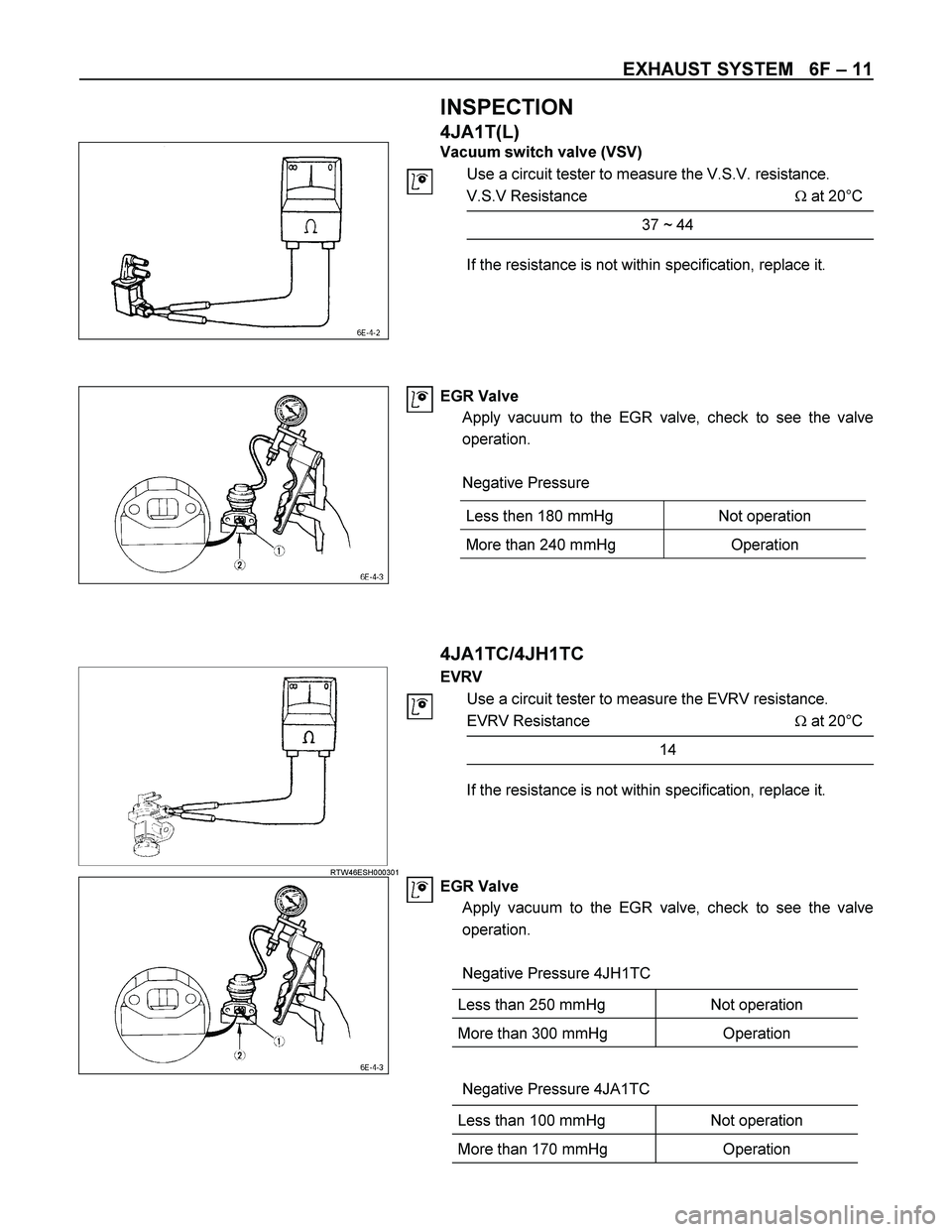
INSPECTION
4JA1T(L)
Vacuum switch valve (VSV)
Use a circuit tester to measure the V.S.V. resistance.
V.S.V Resistance � at 20°C
37 ~ 44
If the resistance is not within specification, replace it.
EGR Valve
Apply vacuum to the EGR valve, check to see the valve
operation.
Negative Pressure
4JA1TC/4JH1TC
RTW46ESH000301
EVRV
Use a circuit tester to measure the EVRV resistance.
EVRV Resistance � at 20°C
14
If the resistance is not within specification, replace it.
EGR Valve
Apply vacuum to the EGR valve, check to see the valve
operation.
Negative Pressure 4JH1TC
Less than 250 mmHg Not operation
More than 300 mmHg Operation
Negative Pressure 4JA1TC
Less than 100 mmHg Not operation
More than 170 mmHg Operation
Less then 180 mmHg Not operation
More than 240 mmHg Operation
Page 1806 of 4264
6F – 12 EXHAUST SYSTEM
EGR COOLER (4JA1TC/4JH1TC EURO-III MODEL)
REMOVAL AND INSTALLATION
RTW46EMF000201
Removal Steps
1. Bolt
2. Gasket
3. Bolt
4. Gasket
5. Bolt
6. Bolt
7. EGR Pipe Assembly
8. Gasket
9. Bolt
10. EGR Cooler Assembly
11. Gasket
12. EGR Cooler Adapter
Removal
1. Bolt
2. Gasket
3. Bolt
4. Gasket
5. Bolt
6. Bolt
7. EGR Pipe Assembly
8. Gasket
9. Bolt
10. EGR Cooler Assembly
11.Gasket
12.EGR Cooler Adapter

Location
Back of the air cleaner case.
Removal Procedure
1. Disconenct the negative battery cable.
2")

High Impedance
Multimeter
(Digital Voltmeter -DVM)
(1) PCMCIA Card
(2")


REMOVAL AND INSTALLATION
RTW46EMF000201
Removal Steps
1. Bolt
2. Gasket
3. Bolt
4. Gasket
5. Bolt
6. B")