Page 3443 of 4264
POWER-ASSISTED STEERING SYSTEM 3B-13
Power Steering Unit Disassembled View
This illustration is based on the RHD model. 440R300003
Legend
(1) Tie-rod End
(2) Lock Nut
(3) Clip
(4) Bellows
(5) Band
(6) Tie-rod Assembly
(7) Oil Line
(8) Inner Ball Joint Assembly
(9) Tab Washer
(10) Mounting Rubber
(11) Housing Assembly
Disassembly
NOTE: The valve housing is made of aluminum and
care should be exercised when clamping in a vise, etc.
to prevent distortion or damage.
1. Loosen lock nut and remove tie-rod end.
2. Remove clip and band, then remove bellows.
3. Remove tie-rod assembly.
To remove, move the boot toward the tie-rod end,
then remove tab washer.
4. Remove oil line, mounting rubber and dust cover.
Inspection and Repair
Inspect the following parts for wear, damage or any
abnormal conditions.
Page 3476 of 4264
3B-46 POWER-ASSISTED STEERING SYSTEM
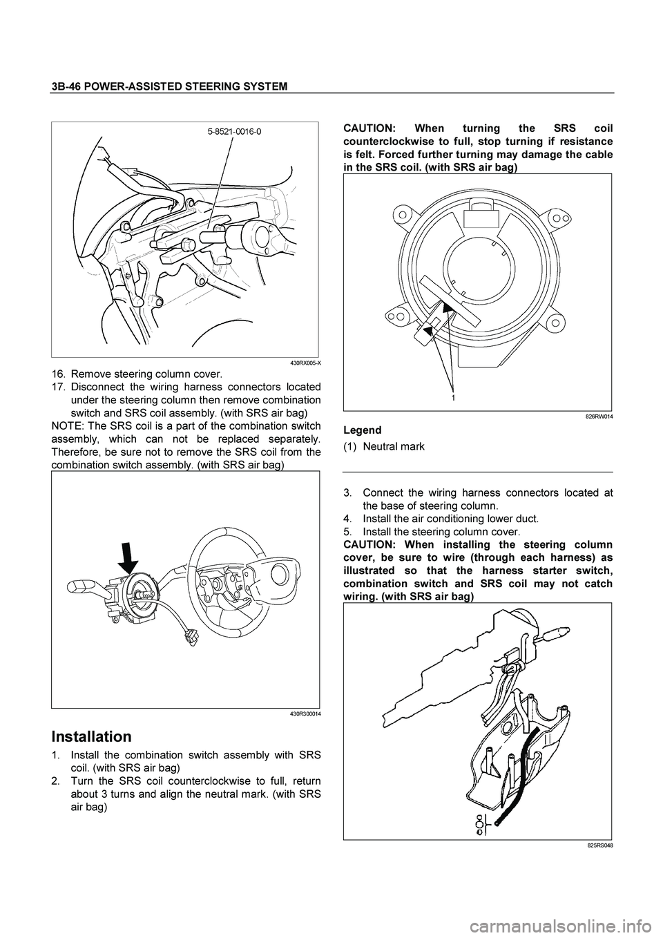
CAUTION:
When turning the SRS coil
counterclockwise to full, stop turning if resistance
is felt. Forced further turning may damage the cable
in the SRS coil.
(with SRS air bag)
826RW014
Legend
(1) Neutral mark
430RX005-X
16. Remove steering column cover.
17. Disconnect the wiring harness connectors located
under the steering column then remove combination
switch and SRS coil assembly. (with SRS air bag)
NOTE: The SRS coil is a part of the combination switch
assembly, which can not be replaced separately.
Therefore, be sure not to remove the SRS coil from the
combination switch assembly. (with SRS air bag)
430R300014
Installation
1. Install the combination switch assembly with SRS
coil. (with SRS air bag)
2. Turn the SRS coil counterclockwise to full, return
about 3 turns and align the neutral mark. (with SRS
air bag)
3. Connect the wiring harness connectors located at
the base of steering column.
4. Install the air conditioning lower duct.
5. Install the steering column cover.
CAUTION:
When installing the steering column
cover, be sure to wire (through each harness) as
illustrated so that the harness starter switch,
combination switch and SRS coil may not catch
wiring.
(with SRS air bag)
825RS048
Page 3505 of 4264
FRONT SUSPENSION 3C-13
Disassembly
1. Install the support fixture (5-8840-0595-0) to the base (5-
8840-003-0).
2. Install the upper adapter (5-8840-0597-0) and the lower
adapter (5-8840-0596-0) to the base and support fixture
assembly.
3. Install the shock absorber assembly to the support fixture.
4. Remove the nut with spring in place.
CAUTION:
Take care not to apply excessive force to the nut during
removal.
CAUTION :
The shock absorbers have been charged with gas at the
factory. Exposure to high temperatures or an open flame
can result in a dangerous explosion.
Keep the shock absorbers away from high temperatures
and open flames.
INSPECTION AND REPAIR
Make all necessary adjustments, repairs, and part replacements if wear, damage, or other problems are discovered
during inspections.
Visual Check
Inspect the following parts for wear, damage or other abnormal
conditions.
�
Shock absorber
�
Rubber bushing
�
Coil spring
Page 3508 of 4264
3C-16 FRONT SUSPENSION
Inspection and Repair
Make necessary correction or parts replacement if
wear, damage, corrosion or any other abnormal
condition are found through inspection.
Check the following parts :
�
Stabilizer bar
�
Rubber bushing
�
Link ball joint
Installation
1. Install rubber bushing.
2. Install stabilizer bar.
3. Install bracket and bolt (5), then tighten it to the
specified torque.
Torque: 25 N�
�� �m (2.5kg�
�� �m/18 lb ft)
4. Install link.
5. Install nut (3), (4), then tighten it to the specified
torque.
Torque: 50 N�
�� �m (5.1kg�
�� �m/37 lb ft)
Page 3510 of 4264
3C-18 FRONT SUSPENSION
6. Remove the stabilizer link nut. Right and left.
7. Remove the wheel speed sensor from the knuckle.
8. Remove back plate.
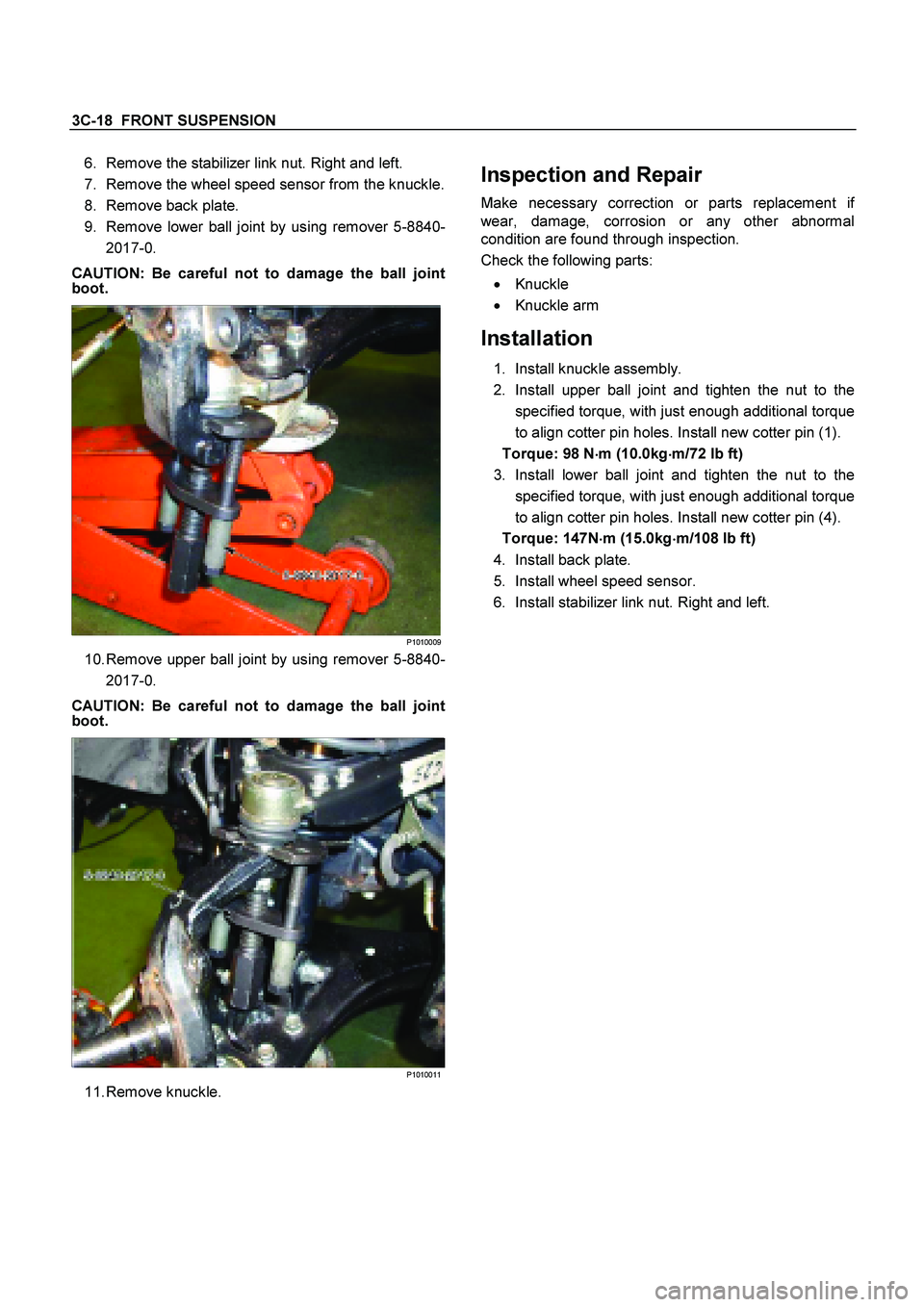
9. Remove lower ball joint by using remover 5-8840- 2017-0.
CAUTION: Be careful not to damage the ball joint
boot.
P1010009
10. Remove upper ball joint by using remover 5-8840-
2017-0.
CAUTION: Be careful not to damage the ball joint
boot.
P1010011
11. Remove knuckle.
Inspection and Repair
Make necessary correction or parts replacement if
wear, damage, corrosion or any other abnormal
condition are found through inspection.
Check the following parts:
�
Knuckle
�
Knuckle arm
Installation
1. Install knuckle assembly.
2. Install upper ball joint and tighten the nut to the
specified torque, with just enough additional torque
to align cotter pin holes. Install new cotter pin (1).
Torque: 98 N �
��
�
m (10.0kg �
��
�
m/72 lb ft)
3. Install lower ball joint and tighten the nut to the specified torque, with just enough additional torque
to align cotter pin holes. Install new cotter pin (4).
Torque: 147N �
��
�
m (15.0kg �
��
�
m/108 lb ft)
4. Install back plate.
5. Install wheel speed sensor.
6. Install stabilizer link nut. Right and left.
Page 3512 of 4264
3C-20 FRONT SUSPENSION
5. Remove nut (8).
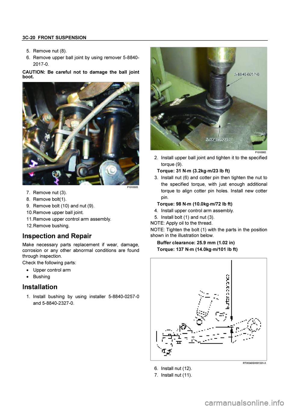
6. Remove upper ball joint by using remover 5-8840-
2017-0.
CAUTION: Be careful not to damage the ball joint
boot.
P1010005
7. Remove nut (3).
8. Remove bolt(1).
9. Remove bolt (10) and nut (9).
10. Remove upper ball joint.
11. Remove upper control arm assembly.
12. Remove bushing.
Inspection and Repair
Make necessary parts replacement if wear, damage,
corrosion or any other abnormal conditions are found
through inspection.
Check the following parts:
�
Upper control arm
�
Bushing
Installation
1. Install bushing by using installer 5-8840-0257-0
and 5-8840-2327-0.
P1010062
2. Install upper ball joint and tighten it to the specified
torque (9).
Torque: 31 N �
��
�
m (3.2kg �
��
�
m/23 lb ft)
3. Install nut (6) and cotter pin then tighten the nut to the specified torque, with just enough additional
torque to align cotter pin holes. Install new cotte
r
pin.
Torque: 98 N �
��
�
m (10.0kg
�
��
�
m/72 lb ft)
4. Install upper control arm assembly.
5. Install bolt (1) and nut (3).
NOTE: Apply oil to the thread.
NOTE: Tighten the bolt (1) with the parts in the position
shown in the illustration below.
Buffer clearance: 25.9 mm (1.02 in)
Torque: 137 N �
��
�
m (14.0kg �
��
�
m/101 lb ft)
RTW340SH001301-X
6. Install nut (12).
7. Install nut (11).
Page 3514 of 4264
3C-22 FRONT SUSPENSION
4. Support lower control arm with a jack.
5. Remove the nut (10).
6. Remove the nut (8).
7. Remove the shock absorber lower end from the
lower control arm.
8. Remove the lower ball joint from the lower control arm.
9. Remove nut (4) and cam plate.
10. Remove cam bolt.
11. Remove lower control arm.
12. Remove bushing.
Inspection and Repair
Make necessary correction or parts replacement if
wear, damage, corrosion or any other abnormal
condition are found through inspection.
Check the following parts:
�
Lower control arm
�
Bushing
Installation
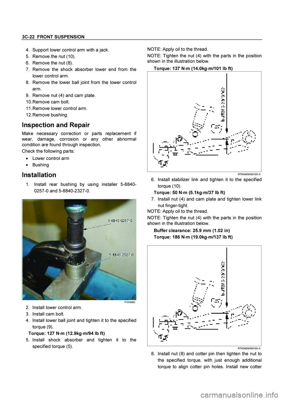
1. Install rear bushing by using installer 5-8840-
0257-0 and 5-8840-2327-0.
P1010063
2. Install lower control arm.
3. Install cam bolt.
4. Install lower ball joint and tighten it to the specified
torque (9).
Torque: 127 N �
��
�
m (12.9kg �
��
�
m/94 lb ft)
5. Install shock absorber and tighten it to the specified torque (5).
NOTE: Apply oil to the thread.
NOTE: Tighten the nut (4) with the parts in the position
shown in the illustration below.
Torque: 137 N �
��
�
m (14.0kg �
��
�
m/101 lb ft)
RTW340SH001301-X
6. Install stabilizer link and tighten it to the specified
torque (10).
Torque: 50 N �
��
�
m (5.1kg �
��
�
m/37 lb ft)
7. Install nut (4) and cam plate and tighten lower link nut finger-tight.
NOTE: Apply oil to the thread.
NOTE: Tighten the nut (4) with the parts in the position
shown in the illustration below.
Buffer clearance: 25.9 mm (1.02 in)
Torque: 186 N �
��
�
m (19.0kg �
��
�
m/137 lb ft)
RTW340SH001301-X
8. Install nut (8) and cotter pin then tighten the nut to
the specified torque, with just enough additional
torque to align cotter pin holes. Install new cotte
r
Page 3517 of 4264
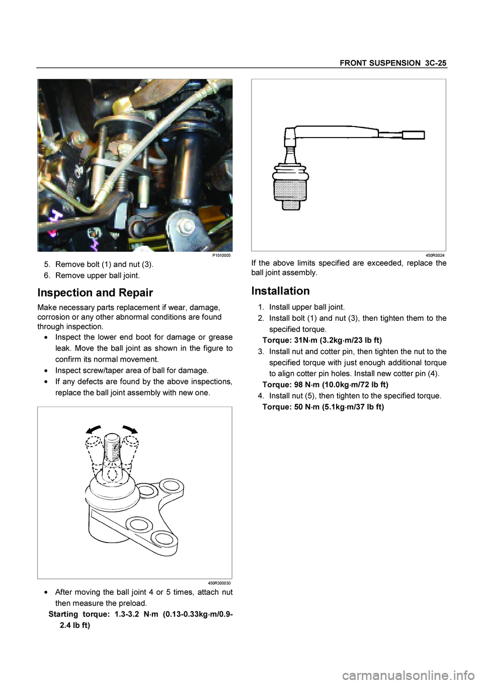
FRONT SUSPENSION 3C-25
P1010005
5. Remove bolt (1) and nut (3).
6. Remove upper ball joint.
Inspection and Repair
Make necessary parts replacement if wear, damage,
corrosion or any other abnormal conditions are found
through inspection.
�
Inspect the lower end boot for damage or grease
leak. Move the ball joint as shown in the figure to
confirm its normal movement.
�
Inspect screw/taper area of ball for damage.
�
If any defects are found by the above inspections,
replace the ball joint assembly with new one.
450R300030
�
After moving the ball joint 4 or 5 times, attach nut
then measure the preload.
Starting torque: 1.3-3.2 N �
��
�
m (0.13-0.33kg �
��
�
m/0.9-
2.4 lb ft)
450RS024
If the above limits specified are exceeded, replace the
ball joint assembly.
Installation
1. Install upper ball joint.
2. Install bolt (1) and nut (3), then tighten them to the specified torque.
Torque: 31N �
��
�
m (3.2kg �
��
�
m/23 lb ft)
3. Install nut and cotter pin, then tighten the nut to the specified torque with just enough additional torque
to align cotter pin holes. Install new cotter pin (4).
Torque: 98 N �
��
�
m (10.0kg
�
��
�
m/72 lb ft)
4. Install nut (5), then tighten to the specified torque. Torque: 50 N �
��
�
m (5.1kg �
��
�
m/37 lb ft)