Page 3541 of 4264
FRONT SUSPENSION 3C-49
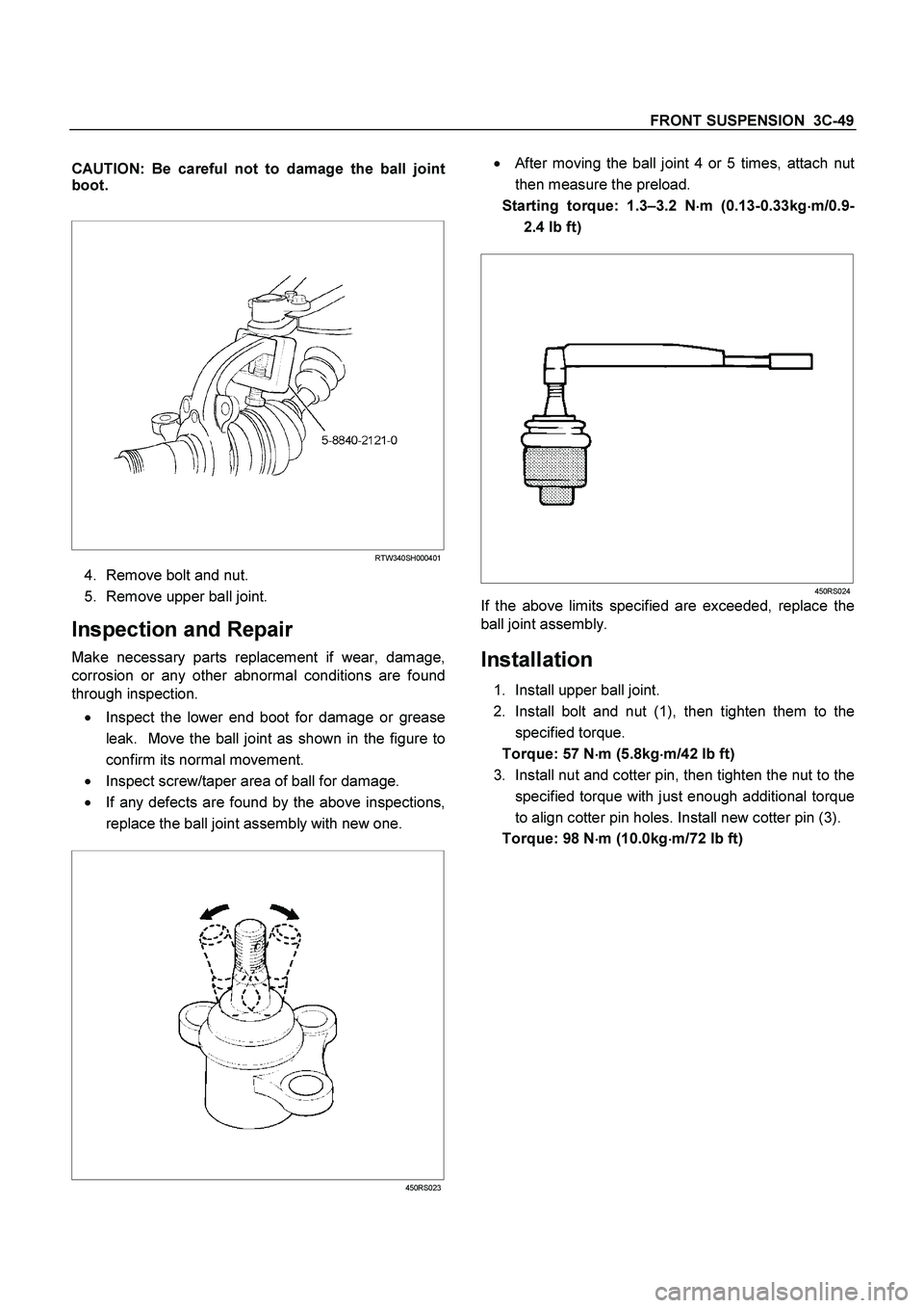
CAUTION: Be careful not to damage the ball joint
boot.
RTW340SH000401
4. Remove bolt and nut.
5. Remove upper ball joint.
Inspection and Repair
Make necessary parts replacement if wear, damage,
corrosion or any other abnormal conditions are found
through inspection.
�
Inspect the lower end boot for damage or grease
leak. Move the ball joint as shown in the figure to
confirm its normal movement.
�
Inspect screw/taper area of ball for damage.
�
If any defects are found by the above inspections,
replace the ball joint assembly with new one.
450RS023
�
After moving the ball joint 4 or 5 times, attach nut
then measure the preload.
Starting torque: 1.3–3.2 N�
�� �m (0.13-0.33kg�
�� �m/0.9-
2.4 lb ft)
450RS024
If the above limits specified are exceeded, replace the
ball joint assembly.
Installation
1. Install upper ball joint.
2. Install bolt and nut (1), then tighten them to the
specified torque.
Torque: 57 N�
�� �m (5.8kg�
�� �m/42 lb ft)
3. Install nut and cotter pin, then tighten the nut to the
specified torque with just enough additional torque
to align cotter pin holes. Install new cotter pin (3).
Torque: 98 N�
�� �m (10.0kg�
�� �m/72 lb ft)
Page 3543 of 4264
FRONT SUSPENSION 3C-51
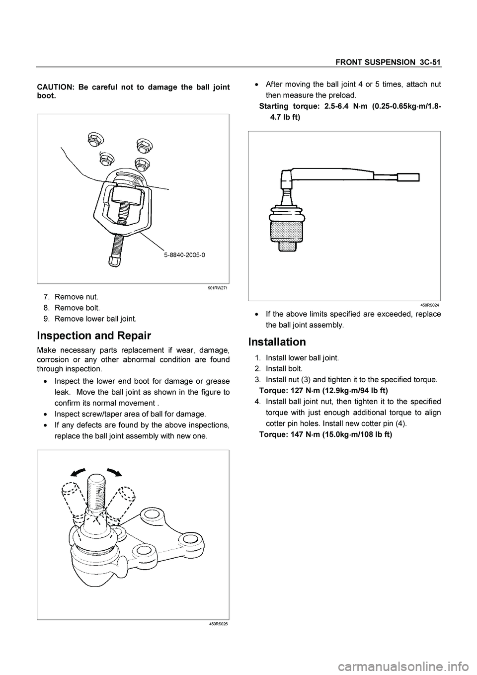
CAUTION: Be careful not to damage the ball joint
boot.
901RW271
7. Remove nut.
8. Remove bolt.
9. Remove lower ball joint.
Inspection and Repair
Make necessary parts replacement if wear, damage,
corrosion or any other abnormal condition are found
through inspection.
�
Inspect the lower end boot for damage or grease
leak. Move the ball joint as shown in the figure to
confirm its normal movement .
�
Inspect screw/taper area of ball for damage.
� If any defects are found by the above inspections,
replace the ball joint assembly with new one.
450RS026
� After moving the ball joint 4 or 5 times, attach nut
then measure the preload.
Starting torque: 2.5-6.4 N�
�� �m (0.25-0.65kg�
�� �m/1.8-
4.7 lb ft)
450RS024
�
If the above limits specified are exceeded, replace
the ball joint assembly.
Installation
1. Install lower ball joint.
2. Install bolt.
3. Install nut (3) and tighten it to the specified torque.
Torque: 127 N�
�� �m (12.9kg�
�� �m/94 lb ft)
4. Install ball joint nut, then tighten it to the specified
torque with just enough additional torque to align
cotter pin holes. Install new cotter pin (4).
Torque: 147 N�
�� �m (15.0kg�
�� �m/108 lb ft)
Page 3544 of 4264
3C-52 FRONT SUSPENSION
Bump Rubber
Bump Rubber and Associated Parts
RTW340MF001001
Legend
(1)
Bolt
(2)
Bump Rubber
Removal
1. Raise the vehicle and support the frame with
suitable safety stands.
2. Remove bolt.
3. Remove bump rubber.
Inspection and Repair
Make necessary correction or parts replacement if
wear, damage, corrosion or any other abnormal
condition are found through inspection.
Check the following parts :
� Bump Rubber
Installation
1. Install bump rubber.
NOTE: Arrow points to be vehicle outer side of afte
r
assembly to vehicle.
2. Install bolt (1), then tighten it to the specified
torque.
Torque: 42 N�
�� �m (4.3kg�
�� �m/31 lb ft)
Page 3563 of 4264
REAR SUSPENSION 3D-7
INSPECTION AND REPAIR
Make correction or parts replacement if wear, damage or their abnormal conditions are found through inspection.
Visual Check
Inspect the following parts for wear, damage, nuts or other
abnormal conditions.
� Leaf spring assembly
� Clip
� Center bolt
� U-bolt
� Spring pin
� Shackle pin
� Shock absorber
� Rubber bumper
� Rubber bushing
� Bump rubber seat
Shackle Pin
Shackle Pin diameter mm (in)
17.93 - 18.00 (0.706 - 0.709)
Spring Pin
Spring Pin Diameter mm (in)
13.8 - 14.0 (0.543 - 0.551)
Shock Absorber
Inspection operation of shock absorber
If no resistance is felt while expanding the shock absorber, that
indicates the absorber is faulty.
Page 3565 of 4264
REAR SUSPENSION 3D-9
LEAF SPRING ASSEMBLY
F03L100004
Disassembly
1. Remove the bushing using a bench press and a suitable
metal fitting.
RTW430SH000101
2. Apply a setting mark across the springs before
disassembling the leaf spring assembly.
F03L100006
3. Use a bench press and remove the center bolt.
� Discard center bolt and install a new one.
465R300001
4. Disassemble the leaf spring assembly.
Inspection and Repair
Inspect leaf spring, bush, clips, liners and center spacer for
wear, damage, rust or other abnormal conditions and if
necessary, repair or replace it.
Page 3580 of 4264
3E-8 WHEELS AND TIRES
INSPECTION AND REPAIR
Make necessary correction or parts replacement if wear, damage or any other abnormal conditions are found
through inspection.
Visual Check
Inspect all disassembled parts for wear, damage or other
abnormal conditions.
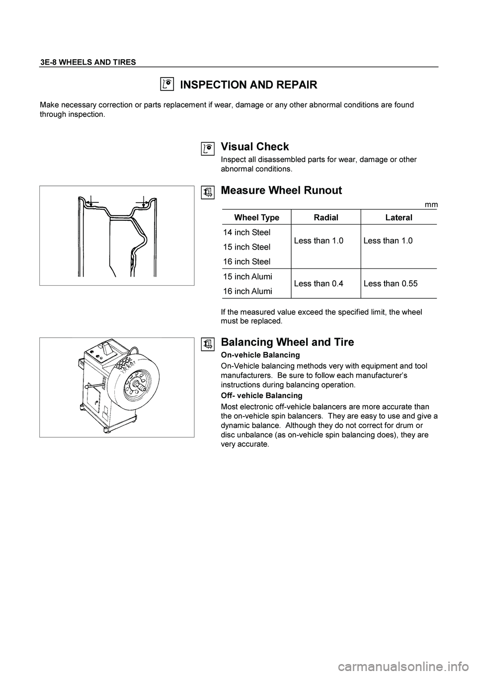
Measure Wheel Runout
mm
Wheel Type Radial Lateral
14 inch Steel
15 inch Steel
16 inch Steel Less than 1.0 Less than 1.0
15 inch Alumi
16 inch Alumi Less than 0.4 Less than 0.55
If the measured value exceed the specified limit, the wheel
must be replaced.
Balancing Wheel and Tire
On-vehicle Balancing
On-Vehicle balancing methods very with equipment and tool
manufacturers. Be sure to follow each manufacturer’s
instructions during balancing operation.
Off- vehicle Balancing
Most electronic off-vehicle balancers are more accurate than
the on-vehicle spin balancers. They are easy to use and give a
dynamic balance. Although they do not correct for drum or
disc unbalance (as on-vehicle spin balancing does), they are
very accurate.
Page 3608 of 4264
7D-20 TRANSFER CASE
Inspection and Repair
1.
Make the necessary repair or parts replacement if
wear, damage or any other abnormal conditions are
found during inspection.
2.
Wash all parts thoroughly in clean solvent. Be sure
all old lubricant, metallic particles, dirt, or foreign
material are removed from the surfaces of every
part. Apply compressed air to each oil feed port and
channel in each case half to remove any
obstructions or cleaning solvent residue.
Inspection and Repair (Transfer
Case Assembly)
When wear, damage, or any other defects are observed
during the inspection, the part or parts must be repaired
or replaced. Wash all the parts with clean detergent,
and check that old oil, metallic particles, dirt, or foreign
materials are completely removed. Blow the air into oil
holes and grooves to remove foreign materials or
residual detergent.
Chain
�
Check whether the face that contacts the sprocket is
free from excessive wear or damage. If defects are
observed, replace the part.
�
If the chain interference mark is found on the inside
wall of the transfer cover or the chain is so slack that
a skipped engagement occurs between the chain
and sprocket, replace the chain.
Sprocket
�
Check whether the sprocket tooth surface is
excessively worn or damaged, and there is evidence
of burrs, chipping, wear, or damage on the gear
spline. Remove minor flaws or scratches with oil
stone. If excessive wear or damage is observed,
replace the part.
�
If excessive wear or damage is observed on the
sprocket inside sliding surface, replace the part.
Gear
�
Check whether the gear tooth surface is excessively
worn or damaged, and there is evidence of burrs,
chipping, wear, or damage on the gear spline.
�
Remove minor flaws or scratches with oil stone. I
f
excessive wear or damage is observed, replace the
part.
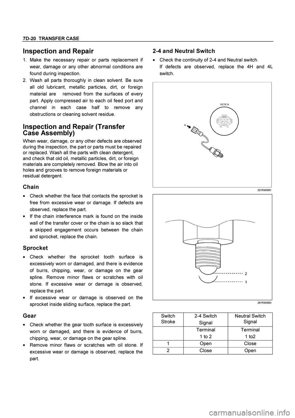
2-4 and Neutral Switch
�
Check the continuity of 2-4 and Neutral switch.
If defects are observed, replace the 4H and 4L
switch.
221R300001
261R300003
Switch
Stroke 2-4 Switch
Signal Neutral Switch
Signal
Terminal
1 to 2 Terminal
1 to2
1 Open Close
2 Close Open
Page 3609 of 4264
TRANSFER CASE 7D-21
Oil Pump
�
Remove foreign materials from the strainer. If the
strainer is damaged, replace it.
If the area into which the shaft is inserted is excessively
worn or damaged, replace the oil pump assembly.
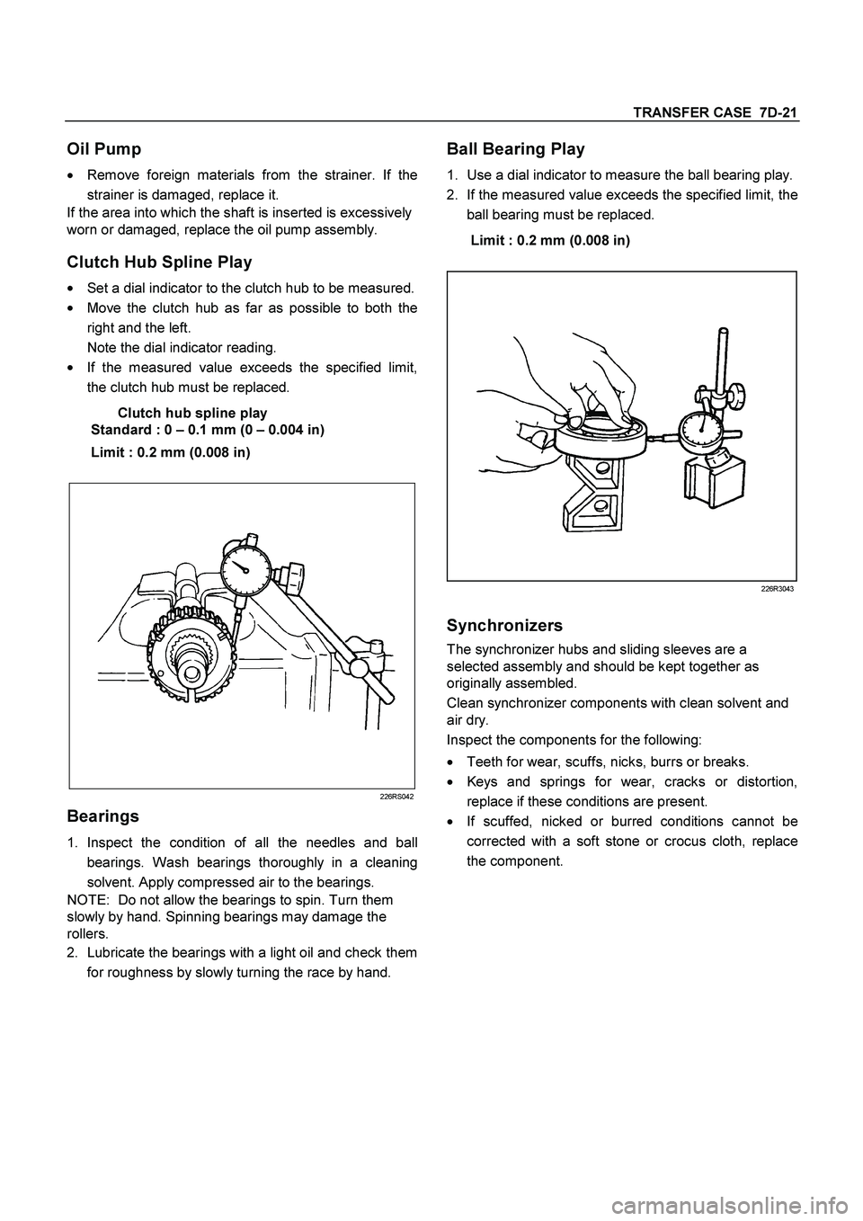
Clutch Hub Spline Play
�
Set a dial indicator to the clutch hub to be measured.
�
Move the clutch hub as far as possible to both the
right and the left.
Note the dial indicator reading.
�
If the measured value exceeds the specified limit,
the clutch hub must be replaced.
Clutch hub spline play
Standard : 0 – 0.1 mm (0 – 0.004 in)
Limit : 0.2 mm (0.008 in)
226RS042
Bearings
1.
Inspect the condition of all the needles and ball
bearings. Wash bearings thoroughly in a cleaning
solvent. Apply compressed air to the bearings.
NOTE: Do not allow the bearings to spin. Turn them
slowly by hand. Spinning bearings may damage the
rollers.
2.
Lubricate the bearings with a light oil and check them
for roughness by slowly turning the race by hand.
Ball Bearing Play
1.
Use a dial indicator to measure the ball bearing play.
2.
If the measured value exceeds the specified limit, the
ball bearing must be replaced.
Limit : 0.2 mm (0.008 in)
226R3043
Synchronizers
The synchronizer hubs and sliding sleeves are a
selected assembly and should be kept together as
originally assembled.
Clean synchronizer components with clean solvent and
air dry.
Inspect the components for the following:
�
Teeth for wear, scuffs, nicks, burrs or breaks.
�
Keys and springs for wear, cracks or distortion,
replace if these conditions are present.
�
If scuffed, nicked or burred conditions cannot be
corrected with a soft stone or crocus cloth, replace
the component.