Page 1003 of 4264
ELECTRICAL-BODY AND CHASSIS 8A-345
REMOVAL AND INSTALLATION
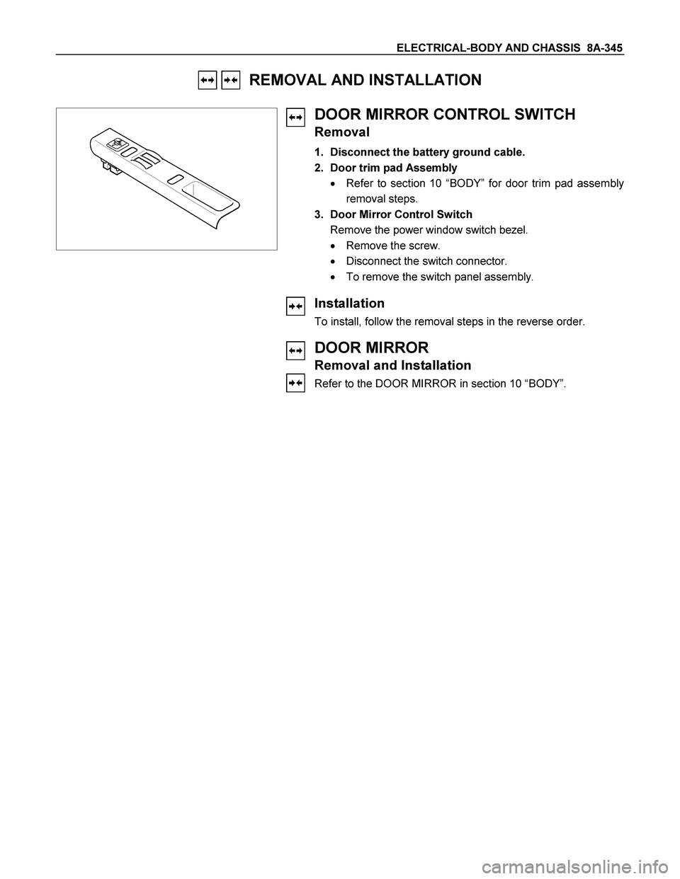
DOOR MIRROR CONTROL SWITCH
Removal
1. Disconnect the battery ground cable.
2. Door trim pad Assembly
� Refer to section 10 “BODY” for door trim pad assembly
removal steps.
3. Door Mirror Control Switch
Remove the power window switch bezel.
� Remove the screw.
� Disconnect the switch connector.
� To remove the switch panel assembly.
Installation
To install, follow the removal steps in the reverse order.
DOOR MIRROR
Removal and Installation
Refer to the DOOR MIRROR in section 10 “BODY”.
Page 1076 of 4264
8A-418 ELECTRICAL-BODY AND CHASSIS
CONNECTOR LIST
No. Connector face No. Connector face
B-1
~
B-6 NOT USED B-17
~
B-19 NOT USED
B-7
Black
Rear defogger relay B-20
WhiteCigar lighter illumination
B-8
Black
Power Window Relay B-21
WhiteCigar lighter
B-9
NOT USED B-22
Black
Cigar lighter
B-10
White
Clock B-23
GreenMeter-A
B-11
�
B-12 NOT USED B-24
Green
Meter-B
B-13
White
Fan switch B-25
~
B-27 NOT USED
B-14
Gray
Audio B-24
GreenGround Driver Side
B-15
NOT USED B-30
~
B-29 NOT USED
B-16
White
Hazard switch B-31
SDM
Page 1084 of 4264
8A-426 ELECTRICAL-BODY AND CHASSIS
No. Connector face No. Connector face
D-1
Brown
Power window motor-RH D-10
WhitePower window switch passenger side
D-2
White
Remote mirror-RH D-11
BrownPower window motor Rear-LH
D-3
Black
Front speaker-RH D-12
WhitePower window switch Rear-LH
D-4
Black
Door lock actuator driver side D-13
BlackRear speaker-LH
D-5
White
Power window driver side D-14
BlackDoor lock actuator Rear-LH
D-6
Brown
Power window motor-LH D-15
BrownPower window motor Rear-RH
D-7
White
Remote mirror-LH D-16
WhitePower window switch-RH
D-8
Black
Speaker-LH D-17
BlackRear speaker-RH
D-9
Black
Door lock actuator passenger side
(keyless & antitheft) D-18
BlackDoor lock actuator Rear-RH
D-9
Black
Door lock actuator passenger side D-19
WhiteRemote mirror switch driver side
Page 1085 of 4264
ELECTRICAL-BODY AND CHASSIS 8A-427
No. Connector face No. Connector face
D-20
White
Power window switch driver side
D-21
White
Tweeter-RH
D-22
White
Tweeter-LH
D-23
White
Door lock & super actuator front (RH)
D-24
White
Key cylinder switch front –(RH)
D-25
White
Door lock & super lock actuator front (LH)
D-26
White
Key cylinder switch front – (LH)
D-27
White
Door lock & super lock actuator RR (RH)
D-28
White
Door lock & super lock actuator RR (LH)
Page 1417 of 4264
4JA1/4JH1 ENGINE DRIVEABILITY AND EMISSIONS 6E–45
FUSE A ND RELAY LOCATION (LHD & RHD)
FUSE
SLOW BLOW FUSE
RELAYNo. Capacity Indication on label No. Capacity Indication on label
1——12 15A CIGER
2 10A ABS 13 15A AUDIO (+B)
3——14 20A DOOR LOCK
4 15A BACK UP 15 10A METER (+B)
5 15A METER 16 10A ROOM
6 10A TURN 17 10A ANTI THEFT
7 15A ELEC.IG 18 15A STOP
8 15A ENGINE 19 15A ACC SOCKET
9 20A FRT WIPER 20 10A STARTER
10 15A EGR 21 10A SRS
11 10A AUDIO
No. Capacity Indication on label
SBF-10 20A RR DEF
SBF-11 30A POWER WINDOW
Connector No. B-7 B-8 B-40
4JA1-TC, 4JH1-TC REAR
DEFOGGERPOWER
WINDOWACC
SOCKET
FUSE BOX
Page 1452 of 4264

6E–80 4JA1/4JH1 ENGINE DRIVEABILITY AND EMISSIONS
Step 3: Simulate the symptom and isolate the
problem
Simulate the symptom and isolate the system by
reproducing all possible conditions suggested in Step 1
while monitoring suspected circuits/components/
systems to isolate the problem symptom. Begin with the
most logical circuit/component.
Isolate the circuit by dividing the suspect system into
simpler circuits. Nex t, confine the problem into a smaller
area of the system. Begin at the most logical point (or
point of easiest access) and thoroughly check the
isolated circuit for the fault, using basic circuit tests.
Hints
You can isolate a circuit by:
Unplugging connectors or removing a fuse to
separate one part of the circuit from another
If only component fails to operate, begin testing the
component
If a number of components do not operate, begin test
at areas of commonality (such as power sources,
ground circuits, switches, main connectors or major
components)
Substitute a known good part from the parts
department or the vehicle system
Try the suspect part in a known good vehicle
See Symptom Simulation Tests on the nex t page for
problem simulation procedures. Refer to service manual
sections 6E and 8A for information about intermittent
diagnosis. Follow procedures for basic circuit testing in
service manual section 8A.
What resources you should use
Whenever appropriate, you should use the following
resources to assist in the diagnostic process:
Service manual
Bulletins
Digital multimeter (with a MIN/MAX feature)
Tech II and Tech II upload function
Circuit testing tools (including connector kits/
harnesses and jumper wires)
Ex perience
Intermittent problem solving simulation methods
Customer complaint check sheet
Symptom Simulation Tests
1. Vibration
This method is useful when the customer complaint
analysis indicates that the problem occurs when the
vehicle/system undergoes some form of vibration.
For connectors and wire harness, slightly shake
vertically and horizontally. Inspect the connector joint
and body for damage. Also, tapping lightly along a
suspected circuit may be helpful.For parts and sensors, apply slight vibration to the part
with a light tap of the finger while monitoring the system
for a malfunction.
2. Heat
This method is important when the complaint suggests
that the problem occurs in a heated environment. Apply
moderate heat to the component with a hair drier or
similar tool while monitoring the system for a
malfunction.
CA UTION: Care must be take to avoid overheating
the component.
3. Water and Moisture
This method may be used when the complaint suggests
that the malfunction occurs on a rainy day or under
conditions of high humidity. In this case, apply water in a
light spray on the vehicle to duplicate the problem.
CA UTION: Care must be take to avoid directly
exposing electrical connections to water.
4. Electrical loads
This method involves turning systems ON (such as the
blower, lights or rear window defogger) to create a load
on the vehicle electrical system at the same time you
are monitoring the suspect circuit/component.
5e. Vehicle Operates as Designed
This condition refers to instances where a system
operating as designed is perceived to be unsatisfactory
or undesirable. In general, this is due to:
A lack of understanding by the customer
A conflict between customer ex pectations and
vehicle design intent
A system performance that is unacceptable to the
customer
What you should do
You can verify that a system is operating as designed
by:
Reviewing service manual functional/diagnostic
checks
Ex amining bulletins and other service information for
supplementary information
Compare system operation to an identical vehicle
If the condition is due to a customer misunderstanding
or a conflict between customer ex pectation and system
operation, you should ex plain the system operation to
the customer.
If the complaint is due to a case of unsatisfactory
system performance, you should contact Technical
Assistance for the latest information.
What resources you should use
Whenever possible, you should use the following
resources to facilitate the diagnostic process:
Page 1469 of 4264
![ISUZU TF SERIES 2004 Workshop Manual 4JA1/4JH1 ENGINE DRIVEABILITY AND EMISSIONS 6E–97
After recording the snapshot in Tech2, transfer the data
from Tech2 to PC by the below procedures.
1. Start TIS2000.
2. Select [Snapshot Upload] on](/manual-img/61/57180/w960_57180-1468.png "ISUZU TF SERIES 2004 Workshop Manual 4JA1/4JH1 ENGINE DRIVEABILITY AND EMISSIONS 6E–97
After recording the snapshot in Tech2, transfer the data
from Tech2 to PC by the below procedures.
1. Start TIS2000.
2. Select [Snapshot Upload] on")
4JA1/4JH1 ENGINE DRIVEABILITY AND EMISSIONS 6E–97
After recording the snapshot in Tech2, transfer the data
from Tech2 to PC by the below procedures.
1. Start TIS2000.
2. Select [Snapshot Upload] on the TIS2000 start
screen.
3. Select [Upload from trouble diagnosis tool (transfer
from diagnosis tester)] or click the corresponding
icon of the tool bar.
4. Select Tech2, and transfer the recorded snapshot
information.
5. Select the transferred snapshot.
6. After ending transfer of the snapshot, data
parameter list is displayed on the screen.3. Snapshot data is displayed with TIS2000
[Snapshot Upload] function.
Snapshot is stored in the PC hard disk or floppy disk,
and can be displayed any time.
Stored snapshot can be displayed by the below
procedures.
1. Start TIS2000.
2. Select [Snapshot Upload] on the TIS2000 start
screen.
3. Select [Open the existing files] or click the
corresponding icon of the tool bar.
4. Select the transferred snapshot.
5. Open the snapshot, to display the data parameter
list on the screen.
Graph display Values and graphs (Max. 3 graphs):
1. Click the icon for graph display. [Graph Parameter]
window opens.
2. Click the first graph icon of the window upper part,
and select one parameter from the list of the window
lower part. Selected parameter is displayed nest to
the graph icon. Graph division can be selected in
the field on the parameter right side.
3. Repeat the same procedures with the 2nd and 3rd
icons.
4. After selecting all parameters to be displayed (Max .
3 parameters), click [OK] button.
5. Parameter selected is displayed in graph form on
the right of the data parameter on the screen.
6. Graph display can be moved with the navigation
icon.
7. For displaying another parameter by graph, click the
parameter of the list, drug the mouse to the display
screen while pressing the mouse button and release
the mouse button. New parameter is displayed at
the position of the previous parameter. For
displaying the graph display screen in full size,
move the cursor upward on the screen. When thecursor is changed to the magnifying glass form, click
the screen. Graph screen is displayed on the whole
screen.
Page 1470 of 4264
6E–98 4JA1/4JH1 ENGINE DRIVEABILITY AND EMISSIONS
Display of graphs on one screen (Max. 6 graphs):
1. Click the 6 graph icon. [Graph Parameter] window
opens.
2. Click the graph icon, select the parameter to be
displayed from the list and change divisions
according to necessity.
3. Repeat the same procedures with the graph icons,
from the 2nd to 6th.
4. Click the [OK] button to display.
5. In this case, parameters are displayed only in graph
form. All parameters are displayed in one graph.
6. The graph display screen can be moved with the
navigation icon.


FUSE
SLOW BLOW FUSE
RELAYNo. Capacity Indication on label No. Capacity Indication on label
1——12 15A CIGER")
![ISUZU TF SERIES 2004 Workshop Manual 6E–98 4JA1/4JH1 ENGINE DRIVEABILITY AND EMISSIONS
Display of graphs on one screen (Max. 6 graphs):
1. Click the 6 graph icon. [Graph Parameter] window
opens.
2. Click the graph icon, select the pa](/manual-img/61/57180/w960_57180-1469.png "ISUZU TF SERIES 2004 Workshop Manual 6E–98 4JA1/4JH1 ENGINE DRIVEABILITY AND EMISSIONS
Display of graphs on one screen (Max. 6 graphs):
1. Click the 6 graph icon. [Graph Parameter] window
opens.
2. Click the graph icon, select the pa")