Page 3045 of 4264

HEATER AND AIR CONDITIONING 1-35
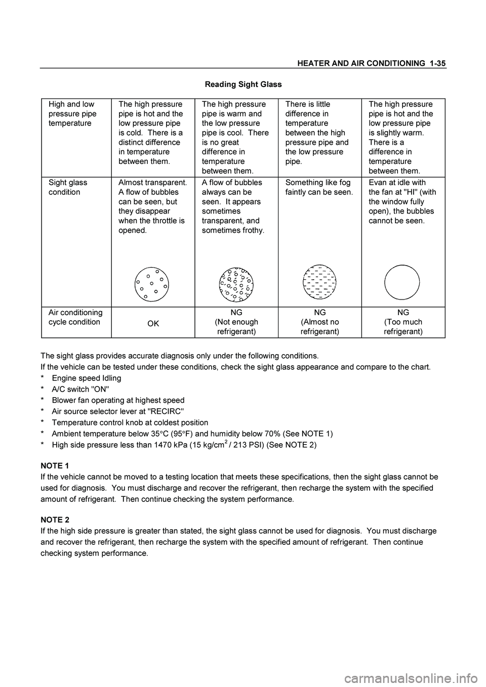
Reading Sight Glass
High and low
pressure pipe
temperature The high pressure
pipe is hot and the
low pressure pipe
is cold. There is a
distinct difference
in temperature
between them. The high pressure
pipe is warm and
the low pressure
pipe is cool. There
is no great
difference in
temperature
between them. There is little
difference in
temperature
between the high
pressure pipe and
the low pressure
pipe. The high pressure
pipe is hot and the
low pressure pipe
is slightly warm.
There is a
difference in
temperature
between them.
Sight glass
condition Almost transparent.
A flow of bubbles
can be seen, but
they disappear
when the throttle is
opened.
A flow of bubbles
always can be
seen. It appears
sometimes
transparent, and
sometimes frothy.
Something like fog
faintly can be seen.
Evan at idle with
the fan at "HI" (with
the window fully
open), the bubbles
cannot be seen.
Air conditioning
cycle condition
OK NG
(Not enough
refrigerant) NG
(Almost no
refrigerant) NG
(Too much
refrigerant)
The sight glass provides accurate diagnosis only under the following conditions.
If the vehicle can be tested under these conditions, check the sight glass appearance and compare to the chart.
* Engine speed Idling
* A/C switch "ON"
* Blower fan operating at highest speed
* Air source selector lever at "RECIRC"
* Temperature control knob at coldest position
* Ambient temperature below 35�
C (95�
F) and humidity below 70% (See NOTE 1)
* High side pressure less than 1470 kPa (15 kg/cm
2 / 213 PSI) (See NOTE 2)
NOTE 1
If the vehicle cannot be moved to a testing location that meets these specifications, then the sight glass cannot be
used for diagnosis. You must discharge and recover the refrigerant, then recharge the system with the specified
amount of refrigerant. Then continue checking the system performance.
NOTE 2
If the high side pressure is greater than stated, the sight glass cannot be used for diagnosis. You must discharge
and recover the refrigerant, then recharge the system with the specified amount of refrigerant. Then continue
checking system performance.
Page 3357 of 4264

ANTITHEFT SYSTEM 11B – 11
RTW48AXF025001
A
DOOR SW-DR
B-73
DOOR SW-PASSDOOR SW-RR RHDOOR SW-RR LH
L-7
0.5
B/W0.5
B/W0.5
B/W
0.5
R/G0.5
R/G0.5
R/G 0.5
R/G0.5
R/G
1
ALARMER C/U
(BUZZER)
1=with ALARMER C/U(BUZZER) only0.5
R/G0.5
R/G0.5
R/W
1.25
B
1.25
B
2.0
B
2.0
B
DOME
LIGHTHORN;
ANTI THEFT
L-91
H-72 L-9
2
RR DEF
(1)
WELD
SPLICE MAP
LIGHT
C-109
BODY-CTR
R-62
R-61
R-11
R-101
R-91 2
H-26L-11
L-1
2
H-1210
H-127R-1R-10R-9
0.5
R/B0.5
R/B
0.5
R/B0.5
R/B
2 2 2
9
H-2614
H-2613
H-26
C-11 10A
AUDIO
2 B-56 3
B-624 2
B-62 B-62
3 B-63
P-6P-5
8
BIG.1IG.2 MAIN
20
B/Y8
B/R
3
W/B
3
W3
W/B
3
B/Y
0.5
R/Y0.5
R/W0.5
R/W0.85R/Y
0.85
O/W
0.85O/W 1.25
LG/W 5
W
P-11
C-108 2
C-108
B1 B2
IG1 IG2 ACCOFF
ST
P-10P-2SBF-180A (4JA1/4JH1)
100A (6VE1/C24SE)
DOOR LOCKC-14
20A
ANTI THEFTC-17
10A
ROOM LAMPC-16
10A SBF-540A50A
SBF-9
BODY ENGINE
JANCTION BLOCK
B-56
8
B-43
2B-43
6
H-134
H-257
D-207
D-206H-104
H-247
D-103
D-104B-44
1B-44
2 4
B-445
B-442
C-117
5
H-12 9
B-43 3
B-43B-55
4B-56C-108
4
H-810 C-117
1 6
H-620
AUTO DOOR LOCK SW.
DRIVER SIDE
AUTO DOOR LOCK SW.
PASSENGER SIDE
0.5
LG/R
0.5
LG/R0.5
LG/R 0.5
R/L
0.5
R/L0.5
R/L
(POWER WINDOW SW.)
LOCK UN LOCK
WITH POWER WINDOW
DOOR LOCK
MOTORB ACC
ANTI THEFT C/U(with KEYLESS ENTRY) STARTER
SW.
3
L
POWER
SUPPLY
RTW48AXF025001
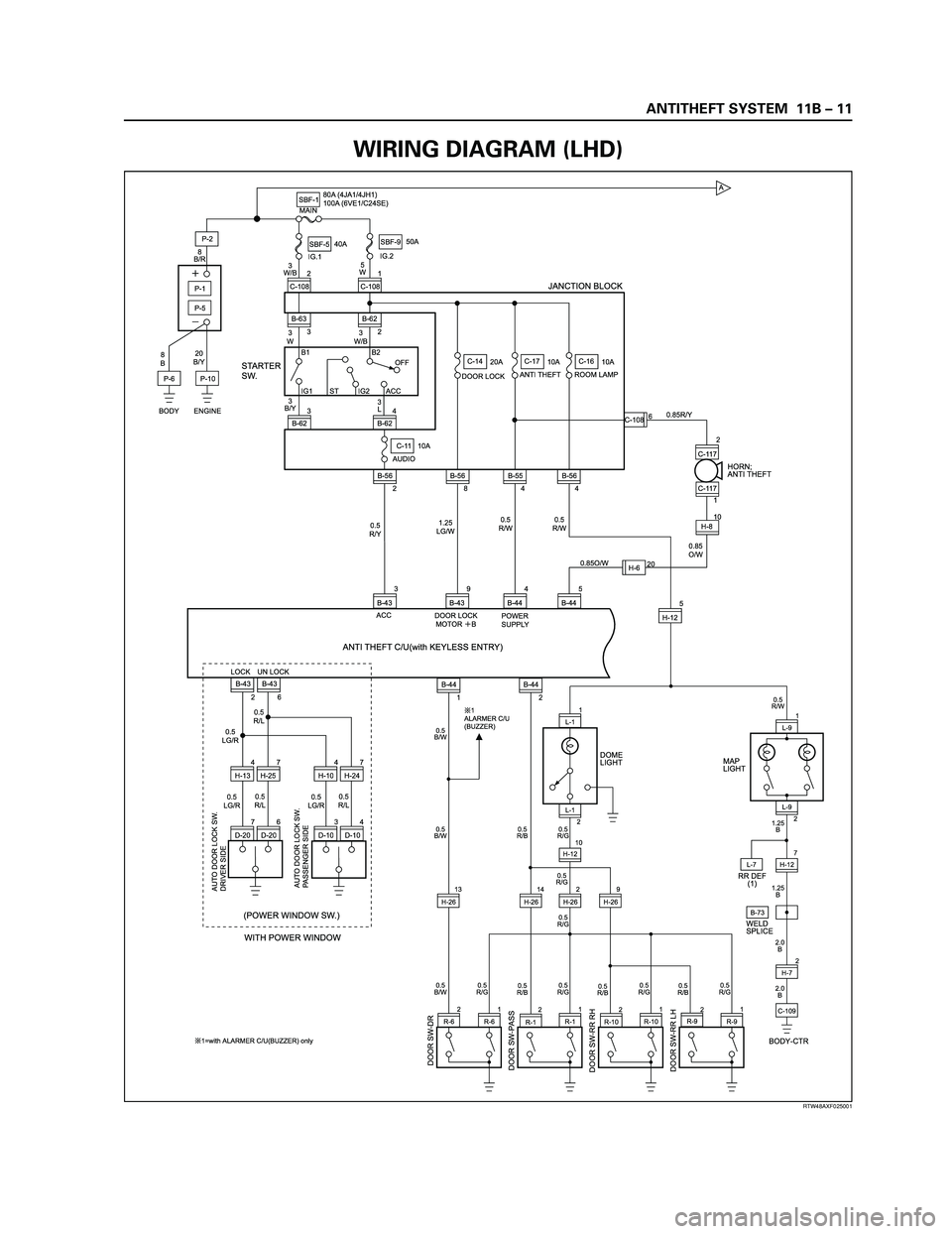
WIRING DIAGRAM (LHD)
Page 3362 of 4264

11B – 16 ANTITHEFT SYSTEM
A
DOOR SW-DR
B-73
DOOR SW-PASSDOOR SW-RR RHDOOR SW-RR LH
L-7
0.5
B/W0.5
B/W0.5
B/W
0.5
R/G0.5
R/G0.5
R/G 0.5
R/G0.5
R/G
1
ALARMER C/U
(BUZZER)
1=with ALARMER C/U(BUZZER) only0.5
R/G0.5
R/G0.5
R/W
1.25
B
1.25
B
2.0
B
2.0
B
DOME
LIGHTHORN;
ANTI THEFT
L-91
H-185 L-9
2
RR DEF
(1)
WELD
SPLICE MAP
LIGHT
C-2
ENGINE �
ROOM RH
R-62
R-61
R-11
R-101
R-91 2
H-26L-11
L-1
2
H-1210
H-127R-1R-10R-9
0.5
R/B0.5
R/B
0.5
R/B0.5
R/B
2 2 2
9
H-2614
H-2613
H-26
C-11 10A
AUDIO
2 B-56 3
B-624 2
B-62 B-62
3 B-63
P-6P-5
8
BIG.1IG.2 MAIN
20
B/Y8
B/R
3
W/B
3
W3
W/B
3
B/Y
0.5
R/Y0.5
R/W0.5
R/W0.85R/Y
1.25
LG/W 5
W
P-11
C-108 2
C-108
B1 B2
IG1 IG2 ACCOFF
ST
P-10P-2SBF-180A (4JA1/4JH1)
100A (6VE1/C24SE)
DOOR LOCKC-14
20A
ANTI THEFTC-17
10A
ROOM LAMPC-16
10A SBF-540A50A
SBF-9
BODY ENGINE
JANCTION BLOCK
B-56
8
B-43
2B-43
6
H-104
H-247
D-207
D-206H-134
H-257
D-103
D-104B-44
1B-44
2 4
B-445
B-442
C-117
5
H-12 9
B-43 3
B-43B-55
4B-56C-108
4
H-181 C-117
1 6
AUTO DOOR LOCK SW.
DRIVER SIDE
AUTO DOOR LOCK SW.
PASSENGER SIDE
0.5
LG/R
0.5
LG/R0.5
LG/R 0.5
R/L
0.5
R/L0.5
R/L
(POWER WINDOW SW.)
LOCK UN LOCK
WITH POWER WINDOW
DOOR LOCK
MOTORB ACC
ANTI THEFT C/U(with KEYLESS ENTRY) STARTER
SW.
3
L
POWER
SUPPLY
RTW48AXF023901
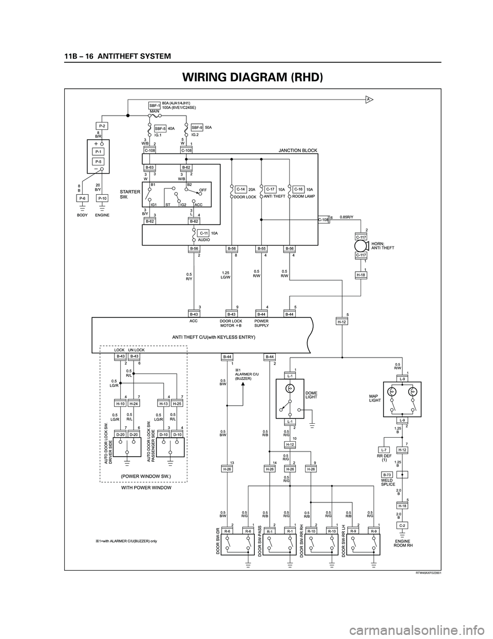
WIRING DIAGRAM (RHD)
Page 3364 of 4264

11B – 18 ANTITHEFT SYSTEM
A
DOOR SW-DR
B-73
DOOR SW-PASSDOOR SW-RR RHDOOR SW-RR LH
L-7
0.5
B/W0.5
B/W0.5
B/W
0.5
R/G0.5
R/G0.5
R/G 0.5
R/G0.5
R/G
1
ALARMER C/U
(BUZZER)
1=with ALARMER C/U(BUZZER) only0.5
R/G0.5
R/G0.5
R/W
1.25
B
1.25
B
2.0
B
2.0
B
DOME
LIGHTHORN;
ANTI THEFT
L-91
H-185 L-9
2
RR DEF
(1)
WELD
SPLICE MAP
LIGHT
C-2
ENGINE �
ROOM RH
R-62
R-61
R-11
R-101
R-91 2
H-26L-11
L-1
2
H-1210
H-127R-1R-10R-9
0.5
R/B0.5
R/B
0.5
R/B0.5
R/B
2 2 2
9
H-2614
H-2613
H-26
C-11 10A
AUDIO
2 B-56 3
B-624 2
B-62 B-62
3 B-63
P-6P-5
8
BIG.1IG.2 MAIN
20
B/Y8
B/R
3
W/B
3
W3
W/B
3
B/Y
0.5
R/Y0.5
R/W0.5
R/W0.85R/Y
1.25
LG/W 5
W
P-11
C-108 2
C-108
B1 B2
IG1 IG2 ACCOFF
ST
P-10P-2SBF-180A (4JA1/4JH1)
100A (6VE1/C24SE)
DOOR LOCKC-14
20A
ANTI THEFTC-17
10A
ROOM LAMPC-16
10A SBF-540A50A
SBF-9
BODY ENGINE
JANCTION BLOCK
B-56
8
B-43
2B-43
6
H-104
H-247
D-207
BD-206H-134
H-257
D-103
D-104B-44
1B-44
2 4
B-445
B-442
C-117
5
H-12 9
B-43 3
B-43B-55
4B-56C-108
4
H-181 C-117
1 6
AUTO DOOR LOCK SW.
DRIVER SIDE
AUTO DOOR LOCK SW.
PASSENGER SIDE
0.5
LG/R
0.5
LG/R0.5
LG/R 0.5
R/L
0.5
R/L0.5
R/L
(POWER WINDOW SW.)
LOCK UN LOCK
WITH POWER WINDOW
DOOR LOCK
MOTORB ACC
ANTI THEFT C/U with SUPER LOCK STARTER
SW.
3
L
POWER
SUPPLY
RTW48AXF025401
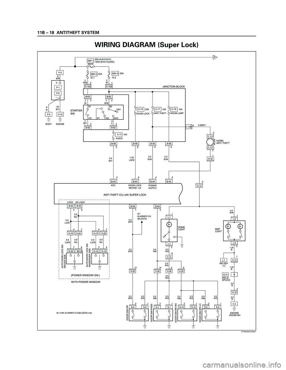
WIRING DIAGRAM (Super Lock)
Page 3705 of 4264
![ISUZU TF SERIES 2004 Workshop Manual TRANSMISSION CONTROL SYSTEM (AW30 –40LE) (V6 3.5L) 7A2-25
Graph display Values and graphs (Max. 3 graphs):
1.
Click the icon for graph display. [Graph
Parameter] window opens. ISUZU TF SERIES 2004 Workshop Manual TRANSMISSION CONTROL SYSTEM (AW30 –40LE) (V6 3.5L) 7A2-25
Graph display Values and graphs (Max. 3 graphs):
1.
Click the icon for graph display. [Graph
Parameter] window opens.](/manual-img/61/57180/w960_57180-3704.png)
TRANSMISSION CONTROL SYSTEM (AW30 –40LE) (V6 3.5L) 7A2-25
Graph display Values and graphs (Max. 3 graphs):
1.
Click the icon for graph display. [Graph
Parameter] window opens.
2.
Click the first graph icon of the window upper part,
and select one parameter from the list of the
window lower part. Selected parameter is
displayed nest to the graph icon. Graph division
can be selected in the field on the parameter right
side.
3.
Repeat the same procedures with the 2nd and 3rd
icons.
4.
After selecting all parameters to be displayed
(Max. 3 parameters), click [OK] button.
5.
Parameter selected is displayed in graph form on
the right of the data parameter on the screen.
6.
Graph display can be moved with the navigation
icon.
7.
For displaying another parameter by graph, click
the parameter of the list, drug the mouse to the
display screen while pressing the mouse button
and release the mouse button. New parameter is
displayed at the position of the previous
parameter. For displaying the graph display screen
in full size, move the cursor upward on the screen.
When the cursor is changed to the magnifying
glass form, click the screen. Graph screen is
displayed on the whole screen.
Page 3706 of 4264
7A2-26 TRANSMISSION CONTROL SYSTEM (AW30 –40LE) (V6 3.5L)
Display of graphs on one screen (Max. 6 graphs):
1.
Click the 6 graph icon. [Graph Parameter] window
opens.
2.
Click the graph icon, select the parameter to be
displayed from the list and change divisions
according to necessity.
3.
Repeat the same procedures with the graph icons,
from the 2nd to 6th.
4.
Click the [OK] button to display.
5.
In this case, parameters are displayed only in
graph form. All parameters are displayed in one
graph.
6.
The graph display screen can be moved with the
navigation icon.
Page 4010 of 4264
![ISUZU TF SERIES 2004 Workshop Manual 7A2-18 DIAGNOSIS (JR405E)
3. Snapshot data is displayed with TIS2000 [Snapshot Upload] function.
Snapshot is stored in the PC hard disk or floppy disk, and can be displayed any time.
Stored ISUZU TF SERIES 2004 Workshop Manual 7A2-18 DIAGNOSIS (JR405E)
3. Snapshot data is displayed with TIS2000 [Snapshot Upload] function.
Snapshot is stored in the PC hard disk or floppy disk, and can be displayed any time.
Stored](/manual-img/61/57180/w960_57180-4009.png)
7A2-18 DIAGNOSIS (JR405E)
3. Snapshot data is displayed with TIS2000 [Snapshot Upload] function.
Snapshot is stored in the PC hard disk or floppy disk, and can be displayed any time.
Stored snapshot can be displayed by the below procedures.
1. Start TIS2000.
2. Select [Snapshot Upload] on the TIS2000 start screen.
3. Select [Open the existing files] or click the corresponding icon of the tool bar.
4. Select the transferred snapshot.
5. Open the snapshot, to display the data parameter list on the screen.
Graph display
Values and graphs (Max. 3 graphs):
1. Click the icon for graph display. [Graph Parameter] window opens.
2. Click the first graph icon of the window upper part, and select one parameter from the list of the window lower
part. Selected parameter is displayed nest to the graph icon. Graph division can be selected in the field on the
parameter right side.
3. Repeat the same procedures with the 2nd and 3rd icons.
4. After selecting all parameters to be displayed (Max. 3 parameters), click [OK] button.
Page 4012 of 4264
7A2-20 DIAGNOSIS (JR405E)
Display of graphs on one screen (Max. 6 graphs):
1. Click the 6 graph icon. [Graph Parameter] window opens.
2. Click the graph icon, select the parameter to be displayed from the list and change divisions according to
necessity.
3. Repeat the same procedures with the graph icons, from the 2nd to 6th.
4. Click the [OK] button to display.
5. In this case, parameters are displayed only in graph form. All parameters are displayed in one graph.
6. The graph display screen can be moved with the navigation icon.