Page 3189 of 4264

MANUAL TRANSMISSION 7B1-25
Inspection and Repair
Make the necessary adjustments, and part
replacements if excessive wear or damage is
discovered during inspection.
Shift Arm Thickness
� Use a micrometer to measure the shift arm
thickness.
If the measured value is less than the specified limit,
the shift arm must be replaced.
Shift Arm Thickness
Standard Limit
1st-2nd 9.60 - 9.85 mm
(0.378 - 0.388 in)
3rd-4th
Rev.5th 9.60 - 9.80 mm
(0.378 - 0.386 in) 9.0 mm
(0.354 in)
230RS006
Detent Spring Free Length
� Use a vernier caliper to measure the detent spring
free length.
If the measured value is less than the specified limit,
the detent spring must be replaced.
Detent Spring Free Length
Standard Limit
26.8 mm (1.06 in) 26.2 mm (1.03 in)
SOUTH AFRICA 5th-Rev Only
Detent Spring Free Length
Standard Limit
Outer 27.6 mm (1.09 in) 27.0 mm (1.06 in)
Inner 26.6 mm (1.05 in) 26.0 mm (1.02 in)
220RS012
Detent Spring Tension
�
Use a spring tester to measure the detent spring
tension.
If the measured value is less than the specified limit,
the detent spring must be replaced.
Detent Spring Tension
Compressed height Standard
20 mm (0.787 in) 87.2 - 97.1 N
(19.6 - 21.8 lb)
220RS013
SOUTH AFRICA 5th-RV Only
Detent Spring Free Length
Compressed Standard
Outer 20 mm (0.787 in) 93.5 – 103.3 N
(21.0 – 23.3 lb)
Inner 20 mm (0.787 in) 26.4 – 36.3 N
(5.9 – 8.2 lb)
Page 3247 of 4264

MANUAL TRANSMISSION 7B1-83
Inspection and Repair
Make the necessary adjustments, and part
replacements if excessive wear or damage is
discovered during inspection.
Shift Arm Thickness
� Use a micrometer to measure the shift arm
thickness.
If the measured value is less than the specified limit,
the shift arm must be replaced.
Shift Arm Thickness
Standard Limit
1st-2nd 9.60 - 9.85 mm
(0.378 - 0.388 in)
3rd-4th
Rev.5th 9.60 - 9.80 mm
(0.378 - 0.386 in) 9.0 mm
(0.354 in)
230RS006
Detent Spring Free Length
�
Use a vernier caliper to measure the detent spring
free length.
If the measured value is less than the specified limit,
the detent spring must be replaced.
Detent Spring Free Length
Standard Limit
26.8 mm (1.06 in) 26.2 mm (1.03 in)
SOUTH AFRICA 5th-Rev Only
Detent Spring Free Length
Standard Limit
Outer 27.6 mm (1.09 in) 27.0 mm (1.06 in)
Inner 26.6 mm (1.05 in) 26.0 mm (1.02 in)
220RS012
Detent Spring Tension
�
Use a spring tester to measure the detent spring
tension.
If the measured value is less than the specified limit,
the detent spring must be replaced.
Detent Spring Tension
Compressed height Standard
20 mm (0.787 in) 87.2 - 97.1 N
(19.6 - 21.8 lb)
220RS013
SOUTH AFRICA 5th-RV Only
Detent Spring Free Length
Compressed Standard
Outer 20 mm (0.787 in) 93.5 – 103.3 N
(21.0 – 23.3 lb)
Inner 20 mm (0.787 in) 26.4 – 36.3 N
(5.9 – 8.2 lb)
Page 3494 of 4264
 MODEL
Front suspension Type Independent wishbone arms, coil spring
with stabilizer bar.
Coil spring")
3C-2 FRONT SUSPENSION
MAIN DATA AND SPECIFICATIONS
4�
�� �2 (EXCEPT HIGH RIDE SUSPENSION) MODEL
Front suspension Type Independent wishbone arms, coil spring
with stabilizer bar.
Coil spring Spring Rate 4JH1-TC / 4JA1-TC / 4JA1-L (ENGINE); 9.62 kg/mm
(94.3 N/mm)
C24SE (ENGINE); 7.94 kg/mm (77.9 N/mm)
Type Gas-sealed. Hydraulic, double acting
Stroke 116.5 mm (4.59 in)
Compressed length 284.0 mm (11.18 in)
Front shock absorber
Extended length 400.5 mm (15.77 in)
Stabilizer bar Diameter 25.0 mm (0.98 in)
4�
�� �2 (HIGH RIDE SUSPENSION) MODEL
Front suspension Type Independent wishbone arms, torsion bar spring
with stabilizer bar.
Length 1142 mm (44.96 in) Torsion bar spring
Diameter 29.0 mm (1.14 in)
Type Gas-sealed. Hydraulic, double acting
Stroke 121.0 mm (4.76 in)
Compressed length 257.0 mm (10.12 in)
Front shock absorber
Extended length 378.0 mm (14.88 in)
Stabilizer bar Diameter 26.0 mm (1.02 in)
4�
�� �4 MODEL
Front suspension Type Independent wishbone arms, torsion bar spring
with stabilizer bar.
Length 1142 mm (44.96 in) Torsion bar spring
Diameter 29.0 mm (1.14 in)
Type Gas-sealed. Hydraulic, double acting
Stroke 121.0 mm (4.76 in)
Compressed length 257.0 mm (10.12 in)
Front shock absorber
Extended length 378.0 mm (14.88 in)
Stabilizer bar Diameter 26.0 mm (1.02 in)
Page 3558 of 4264
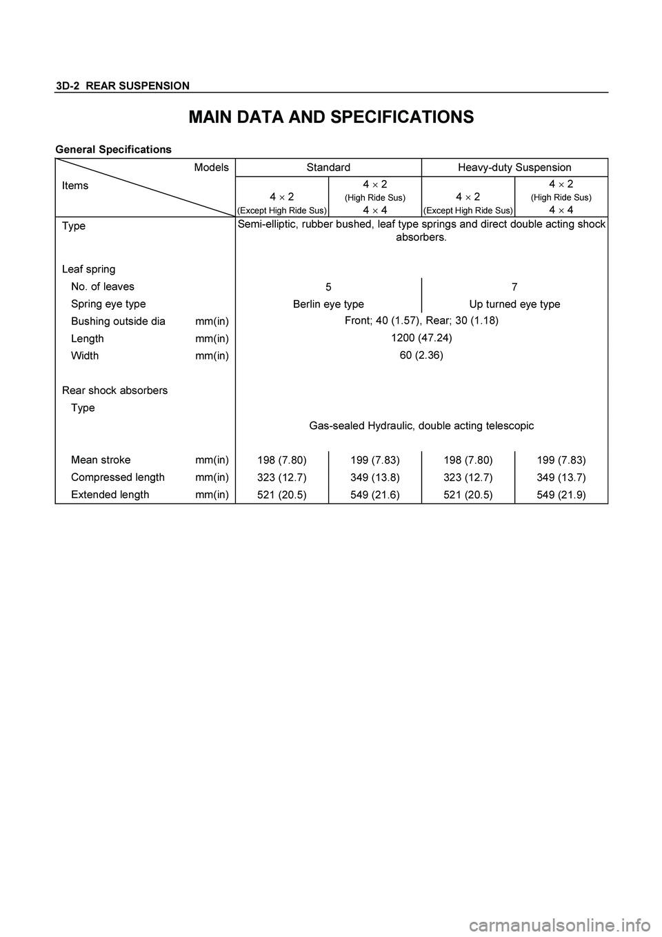
3D-2 REAR SUSPENSION
MAIN DATA AND SPECIFICATIONS
General Specifications
Models Standard Heavy-duty Suspension
Items
4 � 2
(Except High Ride Sus)
4 � 2
(High Ride Sus)
4
� 4
4 � 2 (Except High Ride Sus) 4 � 2
(High Ride Sus)
4
� 4
Type Semi-elliptic, rubber bushed, leaf type springs and direct double acting shock
absorbers.
Leaf spring
No. of leaves
5 7
Spring eye type
Berlin eye type Up turned eye type
Bushing outside dia mm(in) Front; 40 (1.57), Rear; 30 (1.18)
Length mm(in) 1200 (47.24)
Width mm(in) 60 (2.36)
Rear shock absorbers
Type
Gas-sealed Hydraulic, double acting telescopic
Mean stroke mm(in)
198 (7.80) 199 (7.83) 198 (7.80) 199 (7.83)
Compressed length mm(in)
323 (12.7) 349 (13.8) 323 (12.7) 349 (13.7)
Extended length mm(in)
521 (20.5) 549 (21.6) 521 (20.5) 549 (21.9)
Page 3611 of 4264

TRANSFER CASE 7D-23
Detent Spring Free Length
1.
Use a vernier caliper to measure the detent spring
free length.
2.
If the measured value is less than the specified limit,
the detent spring must be replaced.
Detent spring free length
Detent ball
Standard :23.4 mm (0.92 in)
Limit :22.8 mm (0.90 in)
220RW035
Detent Spring Tension
1.
Use a spring tester to measure the detent spring
tension.
2.
If the measured value is less than the specified limit,
the detent spring must be replaced.
Detent ball
Compressed height : 18.7 mm (0.736 in)
Standard : 68.6 ~ 88.2 N (7.0 ~ 9.0 kg/ 15.4 ~ 19.8
lb)
220RS013
Shift Arm
1.
Inspect the shift arms for wear, distortion or scoring.
Replace if these conditions are present.
Shift Arm Thickness
1.
Use a micrometer to measure the shift arm
thickness.
2.
If the measured value is less than the specified limit,
the shift arm must be replaced.
H-L Shift arm thickness
Standard : 7.6-7.85 mm (0.299-0.309 in)
Limit : 7.0 mm (0.276 in)
2-4 Shift arm thickness
Standard : 9.6-9.85 mm (0.378-0.388 in)
Limit : 9.0 mm (0.354 in)
Page 3788 of 4264

Install or Connect
1.
Install the shift cable toward the inside of the cabin
from the bottom of the vehicle.
2.
Push the shift cable into the se")
7A3-32 ON-VEHICLE SERVICE (AW30 –40LE)
Install or Connect
1.
Install the shift cable toward the inside of the cabin
from the bottom of the vehicle.
2.
Push the shift cable into the select lever base.
3.
Connect the shift cable to the select lever.
4.
Fix the shift cable to the bracket.
Install the clip on the marking of shift cable.
5.
Check that the select lever is in the “N ” position.
6.
Check that the transmission is in the “N ” position.
249R300002
7.
Slide the cover in the direction shown by the arrow
(1).
8.
Use an ordinary screwdriver to move the lock piece
from the position indicated by the arrow (2). Continue
to move the lock piece until the adjuster position
begins to change.
P1010012
9.
Connect the shift cable to the manual shaft select
lever at the transmission side.
10.
Insert the lock piece to the adjuster (cable length
adjustment).
11.
Slide the cover on the adjuster and secure lock
piece.
P1010016-2
11.
Press the select lever knob button 5 times.
Then check that the select lever moves smoothly to each of its positions.
13.
Check that the shift position indicated by the select
lever and the actual shift position are the same.
14.
Install the front console and rear console.
15.
Connect the negative battery cable.
16.
Remove the wheel blocks.
Page 3795 of 4264
ON-VEHICLE SERVICE (AW30 –40LE) 7A3-39
Installation
To install, follow the removal steps in reverse order
noting the following point;
1. Reinstall the parts removed with the valve bod
y
assembly to their assigned positions in the
transmission case (check valve assembly, C0
accumulator pistons, etc). Install the valve bod
y
assembly to the transmission case.
Refer to REASSEMBLY OF MAJO
R
COMPONENTS (2).
2. Solenoid clamp bolt
Torque : 7 N �
��
�
m (61 Ib in)
3. Valve body fixing bolts
Each bolt location and length (mm) is indicated in
the figure.
Torque : 10 N �
��
�
m (87 Ib in)
NOTE: Tighten the bolts toward outside equally.
244R200078
4. Oil strainer fixing bolts
Torque : 10 N �
��
�
m (87 Ib in)
5. Oil pan fixing bolts
Torque : 8 N �
��
�
m (69 Ib in)
Page 3820 of 4264

5. Install the second brake drum gasket.
Install a new second brake drum gasket to the
transmission case.
24 0RY 0 001 3
6. Individual piston operation inspection.")
7A4–12 UNIT REPAIR (AW30–40LE)
5. Install the second brake drum gasket.
Install a new second brake drum gasket to the
transmission case.
24 0RY 0 001 3
6. Individual piston operation inspection.
Check for the sound of operation while injecting
compressed air into the oil hole indicated in the
figure.
24 0RY 0 001 4
E nd OFCa llou t
NOTE: When inspecting the direct clutch, check with
the C–0 accumulator piston hole closed. If there is no
noise, disassemble and check the condition of the parts.7. Install the accumulator pistons.
Coat the O–ring with ATF and install it to the
piston.
Install the three springs and four accumulator
pistons to the bore as shown in th figure.
24 0RY 0 0027
mm (in)
Legend
(1) OD direct clutch
(2) Direct clutch
(3) Forward clutch
(4) OD brake
(5) Second coast brake
(6) Second brake
(7) First and reverse brake
(A) C–0 Accumulator piston hole
Piston Outer diameter Height
B–2 36.8 mm (1.449 in) 62.5 mm (2.461 in)
C–2 36.8 mm (1.449 in) 56.6 mm (2.228 in)
B–0 31.8 mm (1.252 in) 52.0 mm (2.047 in)
C–0 29.8 mm (1.173 in) 44.0 mm (1.732 in)
Spring Free length Outer
diameterColor
B–2 74.6 (2.93) 19.7 (0.78) BROWN
C–2
(Outer)68.5 (2.7) 20.2 (0.80) BLUE
C–2 (Inner) 42.1 (1.658) 14.7 (0.579) PINK
B–0 63.6 (2.504) 16.0 (0.630) RED
C–0
(Outer)74.6 (2.937) 20.9 (0.823) ORANGE
C–0 (Inner) 46.0 (1.811) 14.0 (0.551) YELLOW
 7A3-39
Installation
To install, follow the removal steps in reverse order
noting the following point;
1. Reinstall the parts removed with the valve bod
y")