Page 2117 of 4264
3.5L ENGINE DRIVEABILITY AND EMISSIONS 6E-121
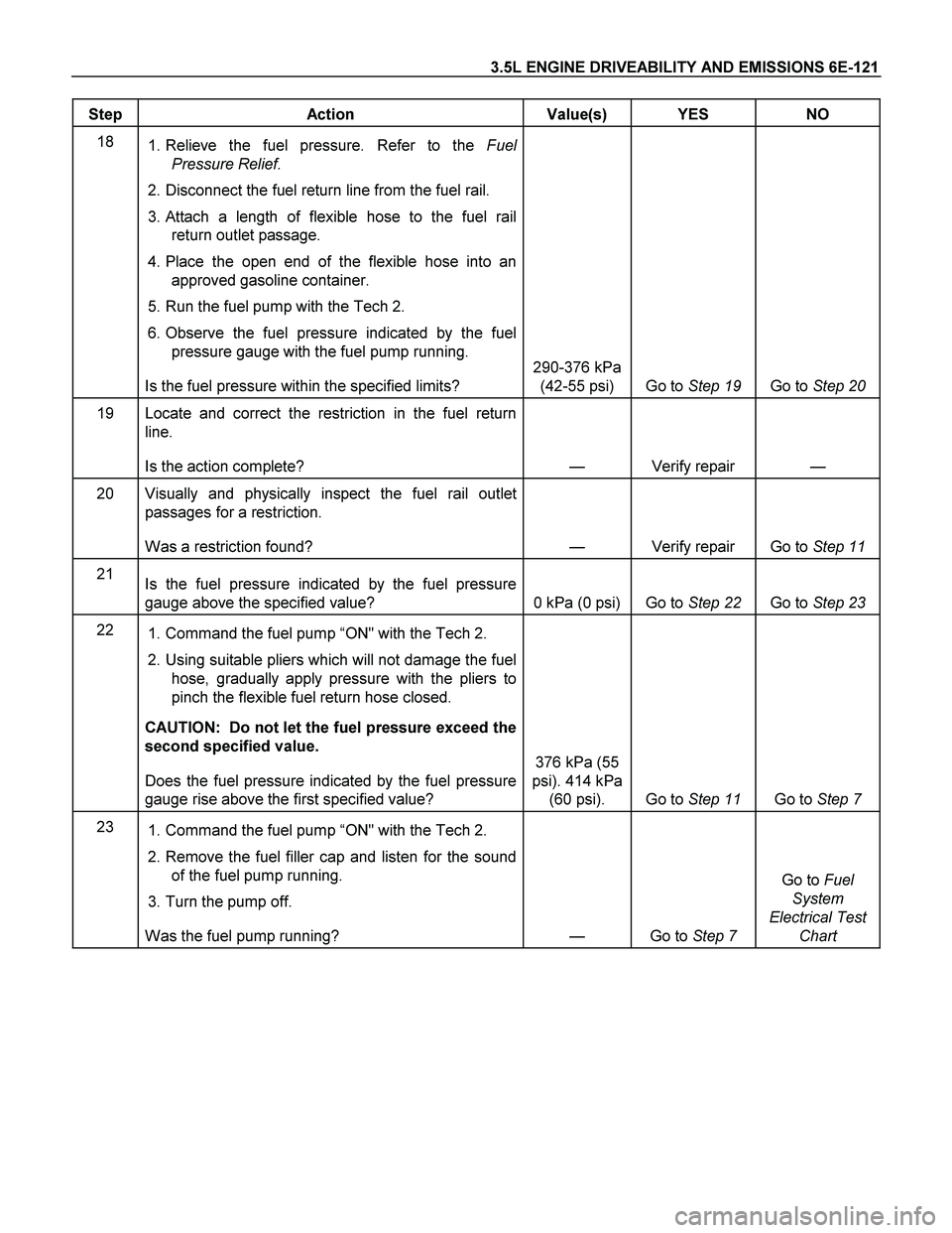
Step Action Value(s) YES NO
18
1. Relieve the fuel pressure. Refer to the Fuel
Pressure Relief.
2. Disconnect the fuel return line from the fuel rail.
3. Attach a length of flexible hose to the fuel rail
return outlet passage.
4. Place the open end of the flexible hose into an
approved gasoline container.
5. Run the fuel pump with the Tech 2.
6. Observe the fuel pressure indicated by the fuel
pressure gauge with the fuel pump running.
Is the fuel pressure within the specified limits? 290-376 kPa
(42-55 psi) Go to Step 19 Go to Step 20
19 Locate and correct the restriction in the fuel return
line.
Is the action complete? — Verify repair —
20 Visually and physically inspect the fuel rail outlet
passages for a restriction.
Was a restriction found? — Verify repair Go to Step 11
21
Is the fuel pressure indicated by the fuel pressure
gauge above the specified value? 0 kPa (0 psi) Go to Step 22 Go to Step 23
22
1. Command the fuel pump “ON" with the Tech 2.
2. Using suitable pliers which will not damage the fuel
hose, gradually apply pressure with the pliers to
pinch the flexible fuel return hose closed.
CAUTION: Do not let the fuel pressure exceed the
second specified value.
Does the fuel pressure indicated by the fuel pressure
gauge rise above the first specified value? 376 kPa (55
psi). 414 kPa
(60 psi). Go to Step 11 Go to Step 7
23
1. Command the fuel pump “ON" with the Tech 2.
2. Remove the fuel filler cap and listen for the sound
of the fuel pump running.
3. Turn the pump off.
Was the fuel pump running? — Go to Step 7 Go to Fuel
System
Electrical Test
Chart
Page 2459 of 4264
ENGINE MECHANICAL (C24SE) 6A-39
Camshaft Housing, Check for Plane Surface
Clean
Sealing surfaces.
Inspection
Check length and width of sealing surface for deformation and
diagnosis for warpage and use straight edge feeler gauge.
Measure
Height of camshaft housing (sealing surface to sealing
surface).
Dimension I: (74.0 mm)
Cylinder Head, Removal and Installation
Important
Only remove cylinder head with engine cold (room
temperature).
Removal
1. Remove the alternator, power steering and V-belts.
Removal
2. Loosen the fastening bolts from alternator.
3. Loosen the lower alternator fastening bolt by swinging
the alternator to the rear.
Removal
4. Remove the front toothed belt cover.
5. Remove the toothed belt from camshaft pulley.
See operation "Timing Check and Adjust".
Page 2476 of 4264
6A-56 ENGINE MECHANICAL (C24SE)
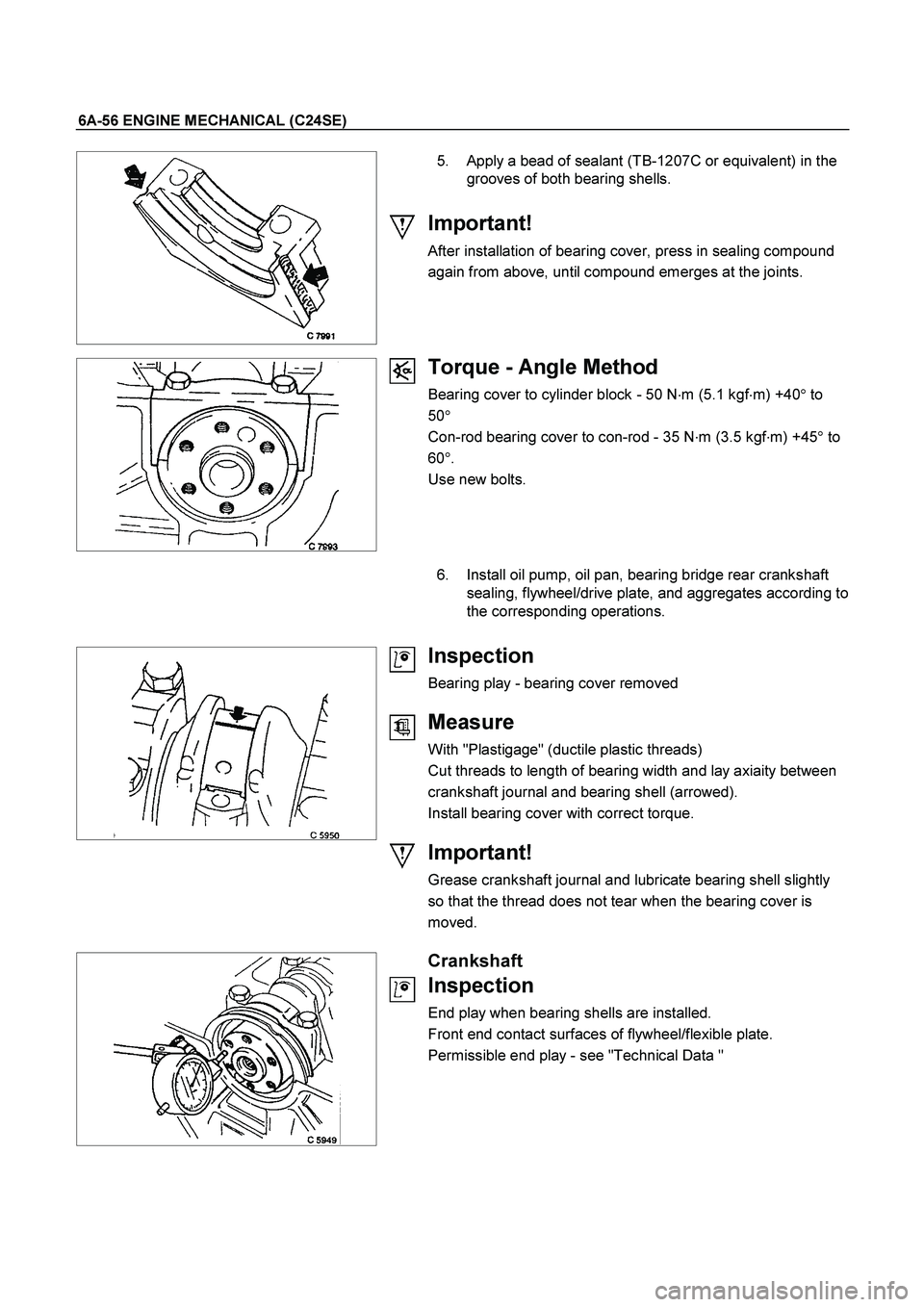
5. Apply a bead of sealant (TB-1207C or equivalent) in the
grooves of both bearing shells.
Important!
After installation of bearing cover, press in sealing compound
again from above, until compound emerges at the joints.
Torque - Angle Method
Bearing cover to cylinder block - 50 N�m (5.1 kgf�m) +40� to
50�
Con-rod bearing cover to con-rod - 35 N�
m (3.5 kgf�
m) +45�
to
60�
.
Use new bolts.
6. Install oil pump, oil pan, bearing bridge rear crankshaft
sealing, flywheel/drive plate, and aggregates according to
the corresponding operations.
Inspection
Bearing play - bearing cover removed
Measure
With "Plastigage" (ductile plastic threads)
Cut threads to length of bearing width and lay axiaity between
crankshaft journal and bearing shell (arrowed).
Install bearing cover with correct torque.
Important!
Grease crankshaft journal and lubricate bearing shell slightly
so that the thread does not tear when the bearing cover is
moved.
Crankshaft
Inspection
End play when bearing shells are installed.
Front end contact surfaces of flywheel/flexible plate.
Permissible end play - see "Technical Data "
Page 2477 of 4264
ENGINE MECHANICAL (C24SE) 6A-57
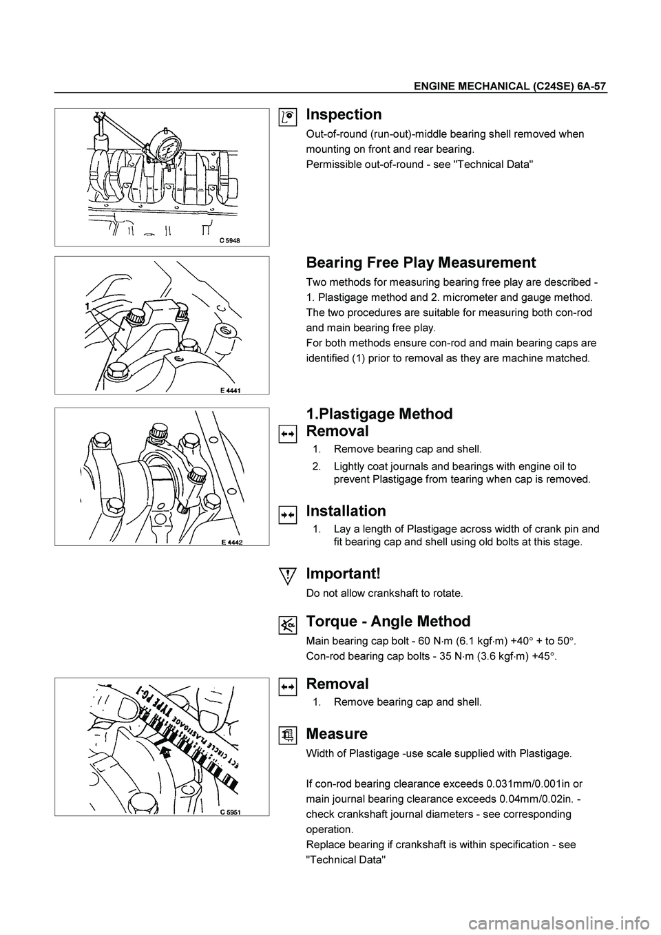
Inspection
Out-of-round (run-out)-middle bearing shell removed when
mounting on front and rear bearing.
Permissible out-of-round - see "Technical Data"
Bearing Free Play Measurement
Two methods for measuring bearing free play are described -
1. Plastigage method and 2. micrometer and gauge method.
The two procedures are suitable for measuring both con-rod
and main bearing free play.
For both methods ensure con-rod and main bearing caps are
identified (1) prior to removal as they are machine matched.
1.Plastigage Method
Removal
1. Remove bearing cap and shell.
2. Lightly coat journals and bearings with engine oil to
prevent Plastigage from tearing when cap is removed.
Installation
1. Lay a length of Plastigage across width of crank pin and
fit bearing cap and shell using old bolts at this stage.
Important!
Do not allow crankshaft to rotate.
Torque - Angle Method
Main bearing cap bolt - 60 N�
m (6.1 kgf�
m) +40�
+ to 50�
.
Con-rod bearing cap bolts - 35 N�
m (3.6 kgf�
m) +45�
.
Removal
1. Remove bearing cap and shell.
Measure
Width of Plastigage -use scale supplied with Plastigage.
If con-rod bearing clearance exceeds 0.031mm/0.001in or
main journal bearing clearance exceeds 0.04mm/0.02in. -
check crankshaft journal diameters - see corresponding
operation.
Replace bearing if crankshaft is within specification - see
"Technical Data"
Page 2499 of 4264
ENGINE MECHANICAL (C24SE) 6A-79
Cylinder Head (continued)
Valve System
Valve lifter valve play compensator
(hydraulic)
Valve rotators
(inlet or outlet) outlet
Valve play
(warm or cold) inlet mm 0
outlet mm 0
Cylinder head height mm 280.3�0.075
Cylinder head bottom, face parallelism mm 0.05
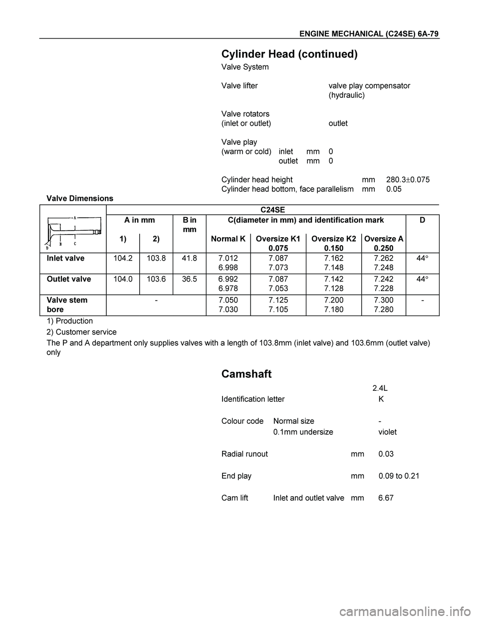
Valve Dimensions
C24SE
A in mm B in
mm C(diameter in mm) and identification mark D
1) 2) Normal K Oversize K1
0.075 Oversize K2
0.150 Oversize A
0.250
Inlet valve 104.2 103.8 41.8 7.012
6.998 7.087
7.073 7.162
7.148 7.262
7.248 44�
Outlet valve 104.0 103.6 36.5 6.992
6.978 7.087
7.053 7.142
7.128 7.242
7.228 44�
Valve stem
bore - 7.050
7.030 7.125
7.105 7.200
7.180 7.300
7.280 -
1) Production
2) Customer service
The P and A department only supplies valves with a length of 103.8mm (inlet valve) and 103.6mm (outlet valve)
only
Camshaft
2.4L
Identification letter K
Colour code Normal size -
0.1mm undersize violet
Radial runout mm 0.03
End play mm 0.09 to 0.21
Cam lift Inlet and outlet valve mm 6.67
Page 2502 of 4264
6A-82 ENGINE MECHANICAL (C24SE)
Crankshaft, Cylinder Block (continued)
Piston Rings
2.4L
Square ring Height mm 1.2
Tapered ring Height mm 1.5
Oil scraper Height mm 2.5
Ring gap offset 180�
Note that the upper steel band ring gap is offset 25 to 50mm to
the left and the lower 25 to 50mm to the right opposite the
intermediate ring gap.
Piston Pin
Length mm 61.5
Diameter mm 21
Type Shrunk into con-rod
Play mm 2.4L
in piston 0.010-0.015
in con-rod none
Installation When installing piston pins,
heat con-rods to approx.
280�C in oil bath. This
temperature should under no
circumstances be exceeded.
Crankshaft, Cylinder Block (continued)
The permissible weight variation of con-rods without piston and
bearing shell inside an engine is 8 g.
As the con-rods do not have balancing studs, reworking is not
possible.
Con-rods can only be replaced in sets.
Page 2504 of 4264
6A-84 ENGINE MECHANICAL (C24SE)
Piston Pins
Dimensions
Length mm
Diameter mm
61.5
21
Type Shank-fit in con-rod
Clearance
In piston mm
In con-rod mm 2.4L
0.010 to 0.015
0
Installation See operation “Con-rod, Replace”
Page 2539 of 4264
ENGINE FUEL (C24SE) 6C-15
Filler Neck
Removal
1. Remove the fuel tank.
NOTE: Refer to "Fuel Tank" in this section.
2. Put a marking the following point as the filler neck
assembly is restored.
� Each joint area of the hose (to restore axial
direction and insertion length of the hose)
� Each fasten area of the clamp (to restore axial
direction and position of the clamp)
� Each bolt in the clamp (to restore fasten length
of bolt in the clamp)
� The band clip (to restore position and fasten
length of the band clip)
NOTE: Cover end of each hose and pipe to prevent any
dust entering.
Installation
1. Align each marking and restore the following point.
� Each joint area of the hose (Restore axial
direction and insertion length of the hose)
� Each fasten area of the clamp (Restore axial
direction and position of the clamp)
� Each bolt in the clamp (Restore fasten length o
f
bolt in the clamp)
Torque: 2.5 N�
�� �m (0.25 kg�
�� �m / 2 lb ft) … filler neck
side except flat deck model.
� The band clip (Restore position and fasten
length of the band clip)
2. Install the fuel tank.
NOTE: Refer to "Fuel Tank" in this section.
Fuel Gauge Unit
Removal and Installation
As for removal and installation of the Fuel Gauge Unit,
refer to “Fuel Tank" of this section 6C as the fuel gauge
unit is combined with the fuel pump and sende
r
assembly.