Page 3911 of 4264
UNIT REPAIR (AW30–40LE) 7A4–103
18. Remove the sleeve(31) with the plungers(32)(33),
spring(34) and washer.
Remove the two plungers(32)(33) from the sleeve.
Remove the primary regulator valve(36) from the
valve body(37).
2 44R20 006 0
Inspection and Repair
1. Inspect strainer
Inspect strainer for residual adhesive and damage,
and clean and replace as necessary.
2 44R20 005 1
2. Inspect valve springs
Check for damage, squareness, rust and distorted
coils.
Measure the spring free length and replace if less
than shown below.
mm (in)
2 44R20 0077
SpringFree
lengthColor
(1) By-pass valve21.3
(0.839 )YELLOW
(2) Steel ball20.5
(0.807 )WHITE
(3) 1–2 shift valve 30.8
(1.213 )PURPLE
(4) Low coast modulator valve30.4
(1.197 )LIGHT
GREEN
(5) Accumulator control valve33.8
(1.331)—
(6) Solenoid modulator valve 26.6
(1.047)LIGHT
BLUE
(7) Cut back valve 34.0
(1.339)DARK
BLUE
(8) Primary regulator valve38.58
(1.519)WITHE
Page 3923 of 4264
UNIT REPAIR (AW30–40LE) 7A4–11 5
16. Remove the retainer (30) for lock-up relay valve with
a magnetic finger by pushing in the sleeve.
2 43R20 007 1
17. Remove the sleeve(31) with the plunger(32),
spring(33) and lock-up relay valve(34).
Remove the lock-up relay valve(34), spring(33) and
plunger(32) from the sleeve(31).
2 43R20 006 5
Inspection and Repair
1. Inspect valve springs
Check for damage, squareness, rust and distorted
coils.
Measure the spring free length and replace if less
than below.
mm (in)
2 43R20 0076
SpringFree
lengthColor
(1) Secondary regulator valve32.9
(1.295)PURPLE
(2) 2–3 shift valve30.8
(1.213)PURPLE
(3) Reverse control valve25.6
(1.008)—
(4) Second coast modulator
valve25.3
(0.996)ORANGE
(5) 3–4 shift valve30.8
(1.213)PURPLE
(6) Lock-up relay valve 23.4
(0.912)RED
Page 4166 of 4264

Install or Connect
1. Install the shift cable toward the inside of the cabin
from the bottom of the vehicle.
2. Push the shift cable into the select lever base")
7A3-14 ON-VEHICLE SERVICE (JR405E)
Install or Connect
1. Install the shift cable toward the inside of the cabin
from the bottom of the vehicle.
2. Push the shift cable into the select lever base.
3. Connect the shift cable to the select lever.
4. Fix the shift cable to the bracket.
Install the clip on the marking of shift cable.
5. Check that the select lever is in the “N” position.
6. Check that the transmission is in the “N” position.
249R300002
7. Slide the cover in the direction shown by the arrow
(1).
8. Use an ordinary screwdriver to move the lock piece
from the position indicated by the arrow (2). Continue
to move the lock piece until the adjuster position
begins to change.
P1010012
9. Connect the shift cable to the manual shaft selec
t
lever at the transmission side.
10. Insert the lock piece to the adjuster (cable length
adjustment).
11. Slide the cover on the adjuster and secure lock
piece.
P1010016-2
11. Press the select lever knob button 5 times.
Then check that the select lever moves smoothly to
each of its positions.
13. Check that the shift position indicated by the selec
t
lever and the actual shift position are the same.
14. Install the front console and rear console.
15. Connect the negative battery cable.
16. Remove the wheel blocks.
Page 4169 of 4264
 7A3-17
Remove or Disconnect
1. Block the wheels.
2. Disconnect the negative battery cable.
3. Drain the fluid.
Refer to “ATF CHANGE” in this section.
4. Rem")
ON-VEHICLE SERVICE (JR405E) 7A3-17
Remove or Disconnect
1. Block the wheels.
2. Disconnect the negative battery cable.
3. Drain the fluid.
Refer to “ATF CHANGE” in this section.
4. Remove the 19 bolts and oil pan.
5. Inspect the bottom of the oil pan and strainer netting
for foreign material (clutch facing and metal
shavings).
If there is an excessive accumulation of foreign
material, the oil strainer must be replaced.
Further inspection is required to determine the
source of the foreign material.
6. Remove the harness assembly (including oil
temperature sensor).
7. Remove the 11 bolts and the solenoid fixing plate.
8. Remove the 6 solenoids and 3 oil pressure switchs.
Inspect
Oil pressure switch
Apply compressed air (392 kPa/4.0 kg/cm2) to the oil
pressure switch to check the oil pressure switch
continuity between the connector and screw.
Oil temperature sensor (harness assembly)
Check the oil temperature sensor resistance between
harness terminals 7 and 6 (ground).
Oil temperature sensor resistance:
2,400~2,600 ohms (20�
�� �C)
244L300011
Solenoid
Measure the resistance of each solenoid.
Resistance:
Brown connector – 3.0~3.4 ohms (20�
�� �C)
Gray connector – 12.0~13.2 ohms (20�
�� �C)
White connector – 12.2~13.4 ohms (20�
�� �C)
Install or connect
1. Install the O-rings to each of the solenoids.
2. Install the 6 solenoids and 3 oil pressure switchs.
Line pressure solenoid bolt torque:
8 N·m (69 lb·in)
Oil pressure switch bolt torque:
4.4 N·m (39 lb·in)
3. Install the solenoid fixing plate together with the
harness brackets.
Number Length (Color)
Solenoid fixing plate bolt
(A)
(B)
4
7
16 mm (0.63 in) (Gold)
45 mm (1.77 in) (Silver)
Bolt torque : 8 N·m (69 lb·in)
4. Install the harness assembly.
5. If removed, install the oil strainer.
Number Length (Color)
Oil strainer bolt
(C)
(D)
9
4
13 mm (0.51 in) (Silver)
45 mm (1.77 in) (Silver)
Bolt torque : 8 N·m (69 lb·in)
6. Install the new gasket and oil pan.
Bolt torque : 8 N·m (69 lb·in)
7. Fill the fluid.
Refer to “ATF CHANGE” in this section.
8. Connect the negative battery cable.
9. Remove the wheel blocks.
Page 4170 of 4264
7A3-18 ON-VEHICLE SERVICE (JR405E)
CONTROL VALVE ASSEMBLY
244L300001
Remove or Disconnect
1. Block the wheels.
2. Disconnect the negative battery cable.
3. Drain the fluid.
Refer to “ATF CHANGE” in this section.
4. Remove the 19 bolts and oil pan.
5. Inspect the bottom of the oil pan and strainer netting
for foreign material (clutch facing and metal
shavings).
If there is an excessive accumulation of foreign
material, the oil strainer must be replaced.
Further inspection is required to determine the
source of the foreign material.
6. Disconnect the 2 harness connectors leading to the
control valve.
7. Remove the 12 bolts and the control valve assembly.
Number of bolts Length
10 (A)
2 (B) 40 mm (1.57 in)
30 mm (1.18 in)
Note:
Take care not to disturb the manual valve (inside the
control valve assembly).
Do not allow the pin to fall free (the pin prevents the
valve from turning).
Page 4171 of 4264
 7A3-19
Install or Connect
1. Align the manual valve and the manual plate of the
transmission case.
43ASSY119
2. Install the control valve assembly and tighten the 12")
ON-VEHICLE SERVICE (JR405E) 7A3-19
Install or Connect
1. Align the manual valve and the manual plate of the
transmission case.
43ASSY119
2. Install the control valve assembly and tighten the 12
fixing bolts to the specified torque.
Number of bolts Length Color
10 (A) 40 mm (1.57 in) Gold
2 (B) 30 mm (1.18 in) Gold
Bolt torque : 8 N·m (69 lb·in)
3. Connect the 2 harness connectors.
4. If removed, install the oil strainer.
Refer to “Solenoids, Oil Pressure Switch and Oil
Temperature Sensor” previously in this section.
5. Install the new gasket and oil pan.
Bolt torque : 8 N·m (69 lb·in)
6. Fill the fluid.
Refer to “ATF CHANGE” in this section.
7. Connect the negative battery cable.
8. Remove the wheel blocks.
FLUSHING THE TRANSMISSION FLUID COOLER AND LINE
The fluid cooler and lines may be flushed under the
following condition. This will help prevent more trouble
after the transmission is repaired.
1. When the abnormal amount of debris are found.
2. When the abnormal wear or chips on gears and
shafts are found while overhauling.
3. When the abnormal clutch facing wear and oil
contamination are found.
Procedures
1. Block the wheels.
2. Disconnect negative battery cable.
3. Raise vehicle and support with suitable safety
stands.
4. Disconnect fluid cooler lines at transmission case
and fluid cooler.
5. Flush and back-flush the fluid cooler and lines using
solvent and compressed air.
Note:
DO NOT exceed 197 kPa (29 psi) air pressure or
damage may result to oil cooler.
6. Remove all remaining solvent from the system with
compressed air.
7. Flush the cooling system again with Automatic
Transmission Fluid (ATF).
After the final flush, connect all lines.
Cooler line joint connector torque :
44 N·m (33 lb·ft)
8. Replenish ATF
9. Start engine to test the system for the free flow o
f
fluid. If the flow is restricted, the cooler assembly o
r
lines must be replaced.
Repeated cleaning and flushing may not remove all
debris from the fluid cooler circuit.
Move the select lever through the various ranges and
return to neutral.
Check for fluid level.
If the fluid level is below the specified range, ATF
must be added.
10. Connect negative battery cable.
11. Remove safety stands.
12. Remove wheel blocks.
Page 4179 of 4264
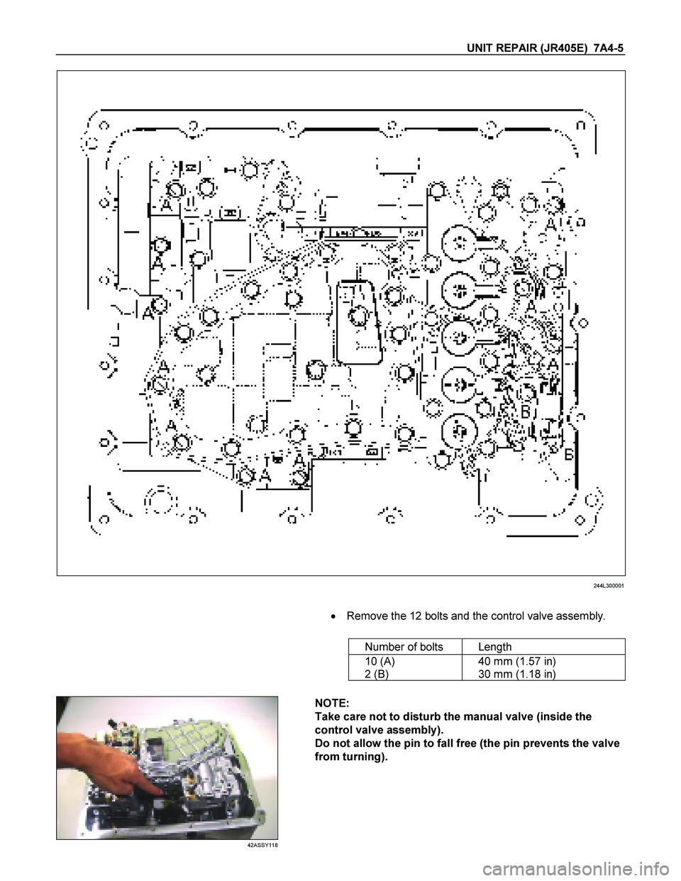
UNIT REPAIR (JR405E) 7A4-5
244L300001
�
Remove the 12 bolts and the control valve assembly.
Number of bolts Length
10 (A)
2 (B) 40 mm (1.57 in)
30 mm (1.18 in)
42ASSY118
NOTE:
Take care not to disturb the manual valve (inside the
control valve assembly).
Do not allow the pin to fall free (the pin prevents the valve
from turning).
Page 4188 of 4264
7A4-14 UNIT REPAIR (JR405E)
Number Length (Color)
Control valve rocket
bolts and nuts (A) 2 (Plus 2 nuts) 50 mm (1.97 in) (Gold)
Upper body and
lower body fixing
bolts
(B) 2 45 mm (1.77 in) (Silver)
(C) 13 35 mm (1.38 in) (Silver)
Line pressure
solenoid fixing bolt
(D) 1 16 mm (0.63 in) (Gold)
Torque: 8 N�
�� �m (69 Ib�
�� �in)
 7A4–103
18. Remove the sleeve(31) with the plungers(32)(33),
spring(34) and washer.
Remove the two plungers(32)(33) from the sleeve.
Remove the primary regulator valve(36)")
 7A4–11 5
16. Remove the retainer (30) for lock-up relay valve with
a magnetic finger by pushing in the sleeve.
2 43R20 007 1
17. Remove the sleeve(31) with the plunger(32),")

CONTROL VALVE ASSEMBLY
244L300001
Remove or Disconnect
1. Block the wheels.
2. Disconnect the negative battery cable.
3. Drain the fluid.
Refer to “AT")

Number Length (Color)
Control valve rocket
bolts and nuts (A) 2 (Plus 2 nuts) 50 mm (1.97 in) (Gold)
Upper body and
lower body fixing
bolts
(B) 2 45 mm (1.77")