Page 3490 of 4264

CAUTION: When turning the SRS coil counte
r")
3B-60 POWER-ASSISTED STEERING SYSTEM
9. Turn the SRS coil counter clockwise to full, return
about 3 turns and align the neutral mark. (with SRS
air bag)
CAUTION: When turning the SRS coil counte
r
clockwise to full, stop turning if resistance is felt.
Forced further turning may damage to the cable in
the SRS coil.
826RW014
10. When installing the steering column cover, be sure to
route each wire harness as illustrated so that the
harnesses do not catch any moving parts.
825RW017
Legend
(1) Steering Column Cover
(2) Starter Switch Harness
(3) Combination Switch Harness
(4) Inflator Module Harness
11. Install steering wheel and align the setting marks
made when removing.
Refer to the adjustment method in case a mark is
not attached in this section.
NOTE: Confirm SRS and Horn harness connector is
fixed by the steering wheel.
RTW33BSH000601
CAUTION: Never apply force to the steering wheel in
direction of the shaft by using a hammer or othe
r
impact tools in an attempt to remove the steering
wheel. The steering shaft is designed as an energy
absorbing unit.
12. Tighten the steering wheel fixing nut to the specified
torque.
Torque: 31 - 39 N�
�� �m (3.2 – 4.0 kg�
�� �m/23 - 29 lb ft)
13. Support the module and carefully connect the
module connector and horn lead, then install inflato
r
module.
NOTE: Pass the lead wire through the tabs on the
plastic cover (wire protector) of inflator to prevent lead
wire from being pinched.
14. Tighten bolts to specified torque.
Torque: 2 - 4 N�
�� �m (0.2 – 0.4 kg�
�� �m/17 - 35 lb in)
15. Install driver knee bolster (reinforcement).
16. Install instrument panel lower cover.
17. Install the engine hood opening lever.
18. Connect the yellow 2-way SRS connector and horn
lead located under the steering column.
19. Connect the battery "-" terminal cable. (with SRS ai
r
bag)
Page 3491 of 4264
POWER-ASSISTED STEERING SYSTEM 3B-61
System Inspection (with SRS air bag)
Turn the ignition switch to "ON" while watching warning
light.
The light should flash 7 times and then go off. If lamp
does not operate correctly, refer to Restraints section.
Page 3550 of 4264
3C-58 FRONT SUSPENSION
4. STIFF STEERING WHEEL
Checkpoint Trouble Cause Countermeasure
Steering gear box or steering
linkage
Steering linkage
Steering gear
Wheel alignment
Replace the part
Replace
Replace
Adjust
Insufficient lubricants or
impurities present; or
excessively worn
Deformed
Worn or damaged
Incorrect
Replace
Stiff or damaged or lack of
grease
OK OK OK OK OK
NG NG NG NG NG
OK
Upper and ball joint
Steering column with turn
signal switch
Replace
Interference abrasion
NG
Tire pressure
Adjust
Improper
NG
Page 3591 of 4264
TRANSFER CASE 7D-3
General Description
RUW34DLF000701
The transfer case is used to provide a means of
providing power flow to the front axle. The transfer case
also provides a means of disconnecting the front axle,
providing better fuel economy and quieter operation
when the vehicle is driven on improved roads where
four wheel drive is not required. In addition, the transfer
case provides an additional gear reduction when placed
in low range, which is useful when difficult off-road
conditions are encountered.
Use the 4WD switch on the center cluster panel to
select the drive range. The 4WD indicator lamp will be
lit when 4WD is selected.
Page 3595 of 4264

TRANSFER CASE 7D-7
Removal
NOTE: Before removing transmission and transfer
assembly from vehicle, change the transfer mode to
2WD using the 4WD push button switch on dash panel.
1.
Disconnect battery ground cable.
2.
Raise and support vehicle with suitable stands. Drain
transfer case fluid.
3. Remove the center exhaust pipe(5). (6VE1 only)
4.
Remove rear propeller shaft (1) and front propelle
r
shaft (2)(3).
NOTE: Apply alignment marks on the flange at both
front and rear sides.
5.
Disconnect harness connectors and clip.
Connector: transfer switch, 2WD-4WD actuator,
speed sensor.
NOTE: Avoid turning the vehicle ignition switch to the
ON position when the 2WD-4WD connector is removed
(battery connected).
If the ignition switch must be turned to the ON position,
the controller must first be removed (memory must be
cleared because the CHECK 4WD INDICATOR will
light).
6.
Remove transfer case (4) from the vehicle.
Installation
1.
Apply a thin coat of molybdenum disulfide grease to
the input shaft spline as shown in the figure.
260R300001
Page 3597 of 4264
TRANSFER CASE 7D-9
For A/T
261R300002
3.
Connect harness connectors and clip.
Connector: transfer switch, 2WD-4WD actuator,
speed sensor.
4. Install center exhaust pipe(5). (6VE1 only)
5.
Install rear propeller shaft (1) and front propelle
r
shaft (2)(3).
Torque: 63 N�
�� �m (6.4 kg�
�� �m/46 lb ft)
Page 3599 of 4264
TRANSFER CASE 7D-11
Transfer Disassembly
RTW47DLF000101
Legend
(7) Neutral Switch ASM
(1) Transfer Case
(8) Speedometer Bush, Plate and Driven Gear
(2) Companion Flange, O-ring and Nut
(9)Transfer Actuator
(3) Stoneguard
(10)Breather Hose
(4) Detent Plug, Spring and Detent Ball
(11) Heat Protector (Except Diesel Engine)
(5) 2-4 Switch ASM
(6) Switch Bracket
Removal
1.
Remove the stoneguard.
2.
Remove the drain plug from the transfer case to
drain the oil.
3.
Remove the parts listed below.
�
Speedometer bush, plate, and speedomete
r
driven gear
�
Breather hose (Between the transfer case and
the transfer actuator assembly)
�
Transfer actuator assembly
�
Switch bracket
Page 3600 of 4264
7D-12 TRANSFER CASE
�
2-4 switch assembly (Gray harness cover)
�
Neutral switch assembly (Black harness cover)
�
Detent plugs, detent springs, and detent balls (2
parts each)
4.
Use the companion flange holder (5-8840-0133-0) to
remove the end nut from the front companion flange.
5.
Remove the bolts attaching the rear cover to the
transfer case.
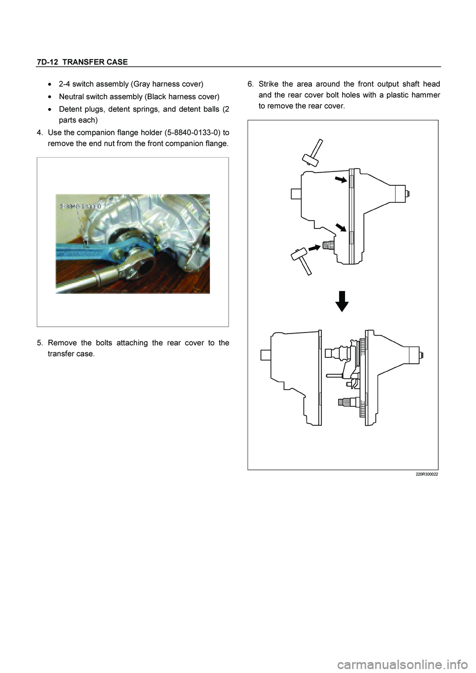
6.
Strike the area around the front output shaft head
and the rear cover bolt holes with a plastic hamme
r
to remove the rear cover.
220R300022

Turn the ignition switch to \"ON\" while watching warning
light.
The light should flash 7 times and then go off. If lamp
does")


. (6VE1 only)")
 Neutral Switch ASM
(1) Transfer Case
(8) Speedometer Bush, Plate and Driven Gear
(2) Companion Flange, O-ring and")