Page 3608 of 4264
7D-20 TRANSFER CASE
Inspection and Repair
1.
Make the necessary repair or parts replacement if
wear, damage or any other abnormal conditions are
found during inspection.
2.
Wash all parts thoroughly in clean solvent. Be sure
all old lubricant, metallic particles, dirt, or foreign
material are removed from the surfaces of every
part. Apply compressed air to each oil feed port and
channel in each case half to remove any
obstructions or cleaning solvent residue.
Inspection and Repair (Transfer
Case Assembly)
When wear, damage, or any other defects are observed
during the inspection, the part or parts must be repaired
or replaced. Wash all the parts with clean detergent,
and check that old oil, metallic particles, dirt, or foreign
materials are completely removed. Blow the air into oil
holes and grooves to remove foreign materials or
residual detergent.
Chain
�
Check whether the face that contacts the sprocket is
free from excessive wear or damage. If defects are
observed, replace the part.
�
If the chain interference mark is found on the inside
wall of the transfer cover or the chain is so slack that
a skipped engagement occurs between the chain
and sprocket, replace the chain.
Sprocket
�
Check whether the sprocket tooth surface is
excessively worn or damaged, and there is evidence
of burrs, chipping, wear, or damage on the gear
spline. Remove minor flaws or scratches with oil
stone. If excessive wear or damage is observed,
replace the part.
�
If excessive wear or damage is observed on the
sprocket inside sliding surface, replace the part.
Gear
�
Check whether the gear tooth surface is excessively
worn or damaged, and there is evidence of burrs,
chipping, wear, or damage on the gear spline.
�
Remove minor flaws or scratches with oil stone. I
f
excessive wear or damage is observed, replace the
part.
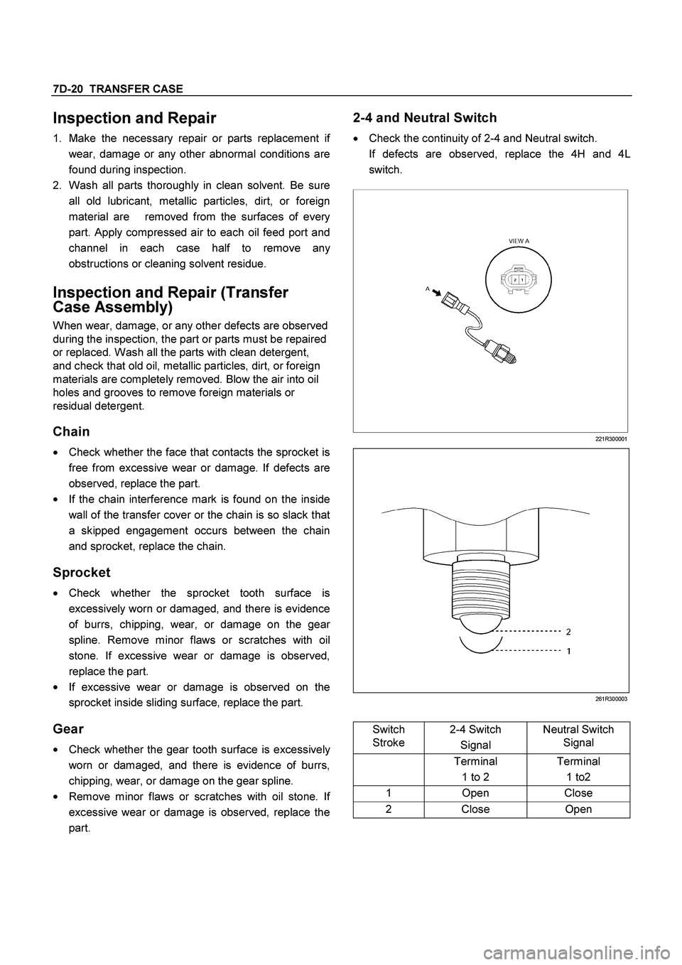
2-4 and Neutral Switch
�
Check the continuity of 2-4 and Neutral switch.
If defects are observed, replace the 4H and 4L
switch.
221R300001
261R300003
Switch
Stroke 2-4 Switch
Signal Neutral Switch
Signal
Terminal
1 to 2 Terminal
1 to2
1 Open Close
2 Close Open
Page 3620 of 4264
7D-32 TRANSFER CASE
43.
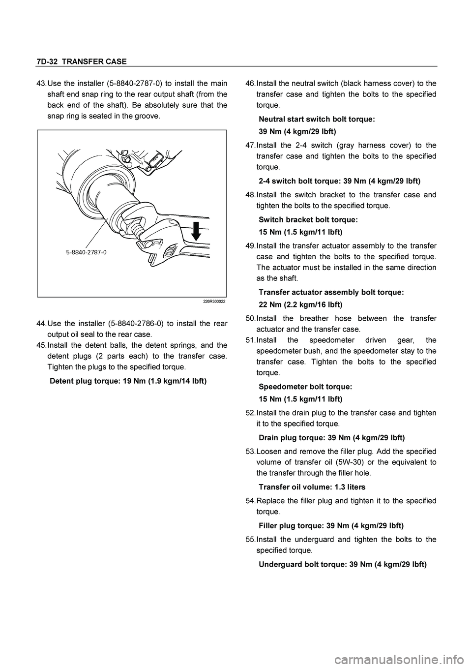
Use the installer (5-8840-2787-0) to install the main
shaft end snap ring to the rear output shaft (from the
back end of the shaft). Be absolutely sure that the
snap ring is seated in the groove.
226R300022
44.
Use the installer (5-8840-2786-0) to install the rea
r
output oil seal to the rear case.
45.
Install the detent balls, the detent springs, and the
detent plugs (2 parts each) to the transfer case.
Tighten the plugs to the specified torque.
Detent plug torque: 19 Nm (1.9 kgm/14 lbft)
46.
Install the neutral switch (black harness cover) to the
transfer case and tighten the bolts to the specified
torque.
Neutral start switch bolt torque:
39 Nm (4 kgm/29 lbft)
47.
Install the 2-4 switch (gray harness cover) to the
transfer case and tighten the bolts to the specified
torque.
2-4 switch bolt torque: 39 Nm (4 kgm/29 lbft)
48.
Install the switch bracket to the transfer case and
tighten the bolts to the specified torque.
Switch bracket bolt torque:
15 Nm (1.5 kgm/11 lbft)
49.
Install the transfer actuator assembly to the transfe
r
case and tighten the bolts to the specified torque.
The actuator must be installed in the same direction
as the shaft.
Transfer actuator assembly bolt torque:
22 Nm (2.2 kgm/16 lbft)
50.
Install the breather hose between the transfe
r
actuator and the transfer case.
51.
Install the speedometer driven gear, the
speedometer bush, and the speedometer stay to the
transfer case. Tighten the bolts to the specified
torque.
Speedometer bolt torque:
15 Nm (1.5 kgm/11 lbft)
52.
Install the drain plug to the transfer case and tighten
it to the specified torque.
Drain plug torque: 39 Nm (4 kgm/29 lbft)
53.
Loosen and remove the filler plug. Add the specified
volume of transfer oil (5W-30) or the equivalent to
the transfer through the filler hole.
Transfer oil volume: 1.3 liters
54.
Replace the filler plug and tighten it to the specified
torque.
Filler plug torque: 39 Nm (4 kgm/29 lbft)
55.
Install the underguard and tighten the bolts to the
specified torque.
Underguard bolt torque: 39 Nm (4 kgm/29 lbft)
Page 3621 of 4264
TRANSFER CASE 7D-33
Main Data and Specifications
General Specifications
Type Synchronized type gears shifting between the 2 and 4 wheel drive mode.
Planetary type gears shifting between “low" and “high".
Control method Remote control with the button switch on the instrument panel for gears
shifting among “2H" , “4H" and “4L".
Gear ratio High; 1.000
Low; 2.482
Oil capacity 1.3 lit. (1.37 U.S. quart)
Type of lubricant BESCO GEAR OIL TRANSAXLE (5W-30)
Refer to chart in Section 0
Torque Specifications
N�m (kg�m/lb ft)
RTW47DLF000201
Page 3627 of 4264
TRANSFER CONTROL SYSTEM 7D1-1
SECTION 7D1
TRANSFER CONTROL SYSTEM
TABLE OF CONTENTS
PAGE
Service Precaution .................................................................................................... 7D1 - 2
General Description ................................................................................................... 7D1 - 3
System Components ................................................................................................. 7D1 - 5
Parts Location ...................................................................................................... 7D1 - 5
Functions of Switch and Indicator Lamp ................................................................. 7D1 - 11
Parts Location ............................................................................................................ 7D1 - 23
Circuit Diagram .......................................................................................................... 7D1 - 27
Connector List ........................................................................................................... 7D1 - 31
Diagnosis .................................................................................................................... 7D1 - 34
Before determining trouble ................................................................................. 7D1 - 34
Memory erasing procedure ....................................................................................... 7D1 - 40
Diagnosis from symptom .......................................................................................... 7D1 - 41
Page 3629 of 4264
TRANSFER CONTROL SYSTEM 7D1-3
General Description
RTW47DLF000301
Transfer Position and Drive Mode
Three drive modes can be selected through operation of 4WD switch.
Transfer Position 4WD SWITCH Mode Drive mode
2H RWD Rear wheel drive
HIGH
4H 4WD (HIGH) High-speed mechanical
lock-up four wheel drive
LOW 4L 4WD (LOW) Low-speed mechanical
lock-up four wheel drive
NEUTRAL 2H & 4L (10 Sec) NEUTRAL Towed by other vehicle
Page 3630 of 4264
7D1-4 TRANSFER CONTROL SYSTEM
Summary of transfer control system
The transfer control system switches between the 2-wheel
drive (2H), 4-wheel drive high-speed (4H), 4-wheel drive low-
speed (4L), and neutral positions electrically when the driver
operate the switches.
This system has following functions.
1. Connection or disconnection of drive force distribution to
the front wheel front shaft (axle shaft) (The drive force
distribution to the front propeller is connected o
r
disconnected with the motor actuator.)
2. Try to repeat the connection or disconnection of the front
wheel drive function as described above.
3. Option: Shift on the fly type only.
Instruction of connection or disconnection of the drive force
transmission between the front wheel axle (axle shaft) and
front wheel
(The motor actuator connects or disconnects the left front
wheel ad front wheel axle (axle shaft).).
4. Shifting of auxiliary transmission gears, connection o
r
disconnection of wheel and engine drive force (4H, 4L,
neutral).
5. Operation of indicator on the instrument panel.
6. Transmission of position signal to other controllers.
Page 3631 of 4264
TRANSFER CONTROL SYSTEM 7D1-5
System Components
Parts Location
Speed sensor
Revolutions of the rear output shaft are decreased and taken
out by the speed/drive/driven gears installed in the transfer
case and the number of revolutions is detected with a speed
sensor.
About 4/3 pulses per revolution of the shaft is output.
4WD switch
The 4WD switch detects the movement of the shift rod driving
the 4�
2 - 4�
4 sleeve.
PUSH open is achieved with the PUSH open switch when the
shift rod is at the 4�2 position.
4�
�� �2 - 4�
�� �4 sleeve & Arm
The 4�2 - 4�4 sleeve moves directly in the 4�4 direction with
the 4�
2 - 4�
4 shift rod, but, when moving in 4�
2 direction, a
Page 3632 of 4264
7D1-6 TRANSFER CONTROL SYSTEM
spring standby mechanism is provided between the rod and
sleeve so that the rod is positioned at the 4�
2 position, while
the sleeve is at the 4�4 position in sometime.
This mechanism is provided to protect the shift mechanism
from the force to prevent the movement of the sleeve
(torsional torque etc. of the drive system). By releasing the
preventive force, the sleeve can move to 4�
2 state by the
spring force.
Neutral switch
The neutral switch detects the movement of the shift rod
driving the high-low sleeve.
PUSH close is achieved with the PUSH close switch when the
shift rod is positioned between the High and the Low, that is,
at the neutral state.
High-Low Sleeve & Arm
The spring standby mechanism is provided for the high-low
sleeve in both directions of the high-low shift rod. For this
reason, the rod position and the actual sleeve position may be
offset in some cases.
This system is provided to protect the shift mechanism from
the collision due to coincidence of the high and low phases of
the engaged splines. By giving rotational force to the
preventing phase coincidence, the splines are moved to the
proper engagement position by the spring force.
Shift actuator
The output shaft is rotated by the built-in motor and the
transfer position is switched.
Detection (limit) switches to detect the rotating angle of the
output shaft is provided to the actuator at 4 positions, which
are connected to the transfer controller through the vehicle
harness to constantly transmit the actuator operating angle
and changes in its transfer status.
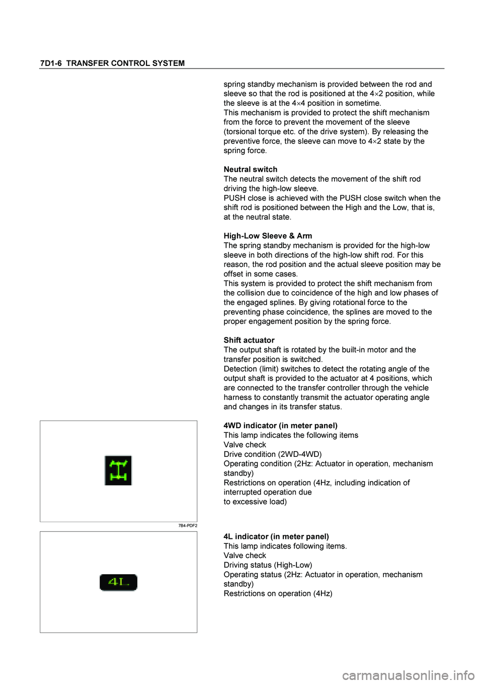
7B4-PDF2
4WD indicator (in meter panel)
This lamp indicates the following items
Valve check
Drive condition (2WD-4WD)
Operating condition (2Hz: Actuator in operation, mechanism
standby)
Restrictions on operation (4Hz, including indication of
interrupted operation due
to excessive load)
4L indicator (in meter panel)
This lamp indicates following items.
Valve check
Driving status (High-Low)
Operating status (2Hz: Actuator in operation, mechanism
standby)
Restrictions on operation (4Hz)