Page 3476 of 4264
3B-46 POWER-ASSISTED STEERING SYSTEM
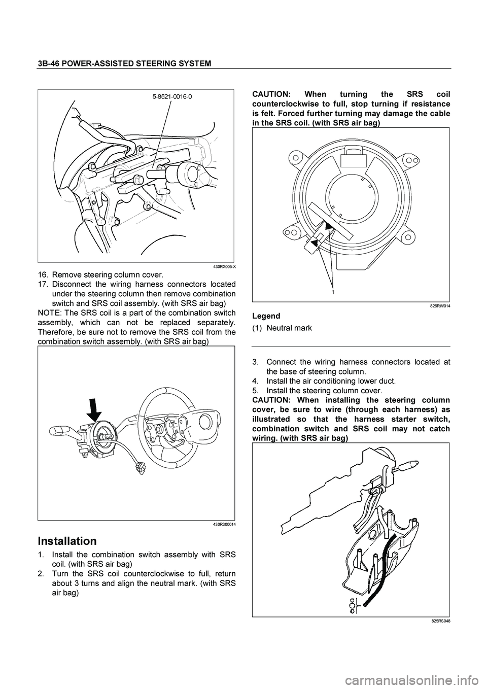
CAUTION:
When turning the SRS coil
counterclockwise to full, stop turning if resistance
is felt. Forced further turning may damage the cable
in the SRS coil.
(with SRS air bag)
826RW014
Legend
(1) Neutral mark
430RX005-X
16. Remove steering column cover.
17. Disconnect the wiring harness connectors located
under the steering column then remove combination
switch and SRS coil assembly. (with SRS air bag)
NOTE: The SRS coil is a part of the combination switch
assembly, which can not be replaced separately.
Therefore, be sure not to remove the SRS coil from the
combination switch assembly. (with SRS air bag)
430R300014
Installation
1. Install the combination switch assembly with SRS
coil. (with SRS air bag)
2. Turn the SRS coil counterclockwise to full, return
about 3 turns and align the neutral mark. (with SRS
air bag)
3. Connect the wiring harness connectors located at
the base of steering column.
4. Install the air conditioning lower duct.
5. Install the steering column cover.
CAUTION:
When installing the steering column
cover, be sure to wire (through each harness) as
illustrated so that the harness starter switch,
combination switch and SRS coil may not catch
wiring.
(with SRS air bag)
825RS048
Page 3478 of 4264
3B-48 POWER-ASSISTED STEERING SYSTEM
13. Align the each snap stud of driver air bag to the hole
of steering wheel. (with SRS air bag)
060R300030
060R300020
14. Push the SRS air bag area1 and area2. At that time
confirm the audible noise of each stud. (with SRS ai
r
bag)
060R300036
15. Enable the SRS (Refer to "Enabling the SRS" in this
section). (with SRS air bag)
16. Install driver knee bolster (reinforcement).
17. Install instrument panel lower cover then Install the
engine hood opening lever.
18. Connect the SRS connector. (with SRS air bag)
19. Connect the battery "-" terminal cable. (with SRS ai
r
bag)
20. Turn the ignition switch to "ON" while watching
warning light and check the light should flash 7 times
and then go off. If lamp does not operate correctly,
refer to Restraints section.
Page 3479 of 4264
POWER-ASSISTED STEERING SYSTEM 3B-49
Lock Cylinder
Lock Cylinder and Associated Parts
This illustration is based on the RHD model.
RTW43BLF000701
Legend
(1) Steering Column Cover
(2) Steering Wheel
(3) Inflator Module or Horn pad
(4) Combination Switch and SRS Coil Assembly
(5) Steering Column Assembly
(6) Lock Cylinder Assembly
(7) Instrument Panel Lower Cover
(8) Driver Knee Bolster (reinforcement)
Removal
1. Turn the steering wheel so that the vehicle's wheels
are pointing straight ahead.
2. Turn the ignition switch to "LOCK".
3. Disconnect the battery "-" terminal cable, and wait a
t
least 5 minutes. (with SRS air bag)
4. Disconnect the yellow 2-way SRS connector located
under the steering column. (with SRS air bag)
Page 3482 of 4264
3B-52 POWER-ASSISTED STEERING SYSTEM
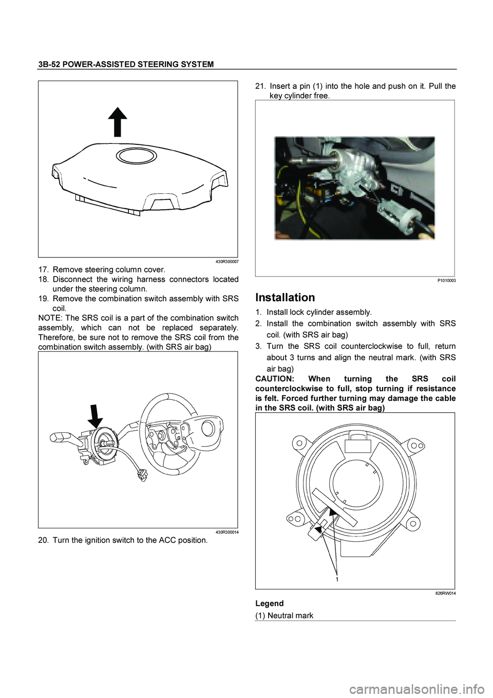
430R300007
17. Remove steering column cover.
18. Disconnect the wiring harness connectors located
under the steering column.
19. Remove the combination switch assembly with SRS
coil.
NOTE: The SRS coil is a part of the combination switch
assembly, which can not be replaced separately.
Therefore, be sure not to remove the SRS coil from the
combination switch assembly. (with SRS air bag)
430R300014
20. Turn the ignition switch to the ACC position.
21. Insert a pin (1) into the hole and push on it. Pull the
key cylinder free.
P1010003
Installation
1. Install lock cylinder assembly.
2. Install the combination switch assembly with SRS
coil. (with SRS air bag)
3. Turn the SRS coil counterclockwise to full, return
about 3 turns and align the neutral mark. (with SRS
air bag)
CAUTION:
When turning the SRS coil
counterclockwise to full, stop turning if resistance
is felt. Forced further turning may damage the cable
in the SRS coil.
(with SRS air bag)
826RW014
Legend
(1) Neutral mark
Page 3484 of 4264
3B-54 POWER-ASSISTED STEERING SYSTEM
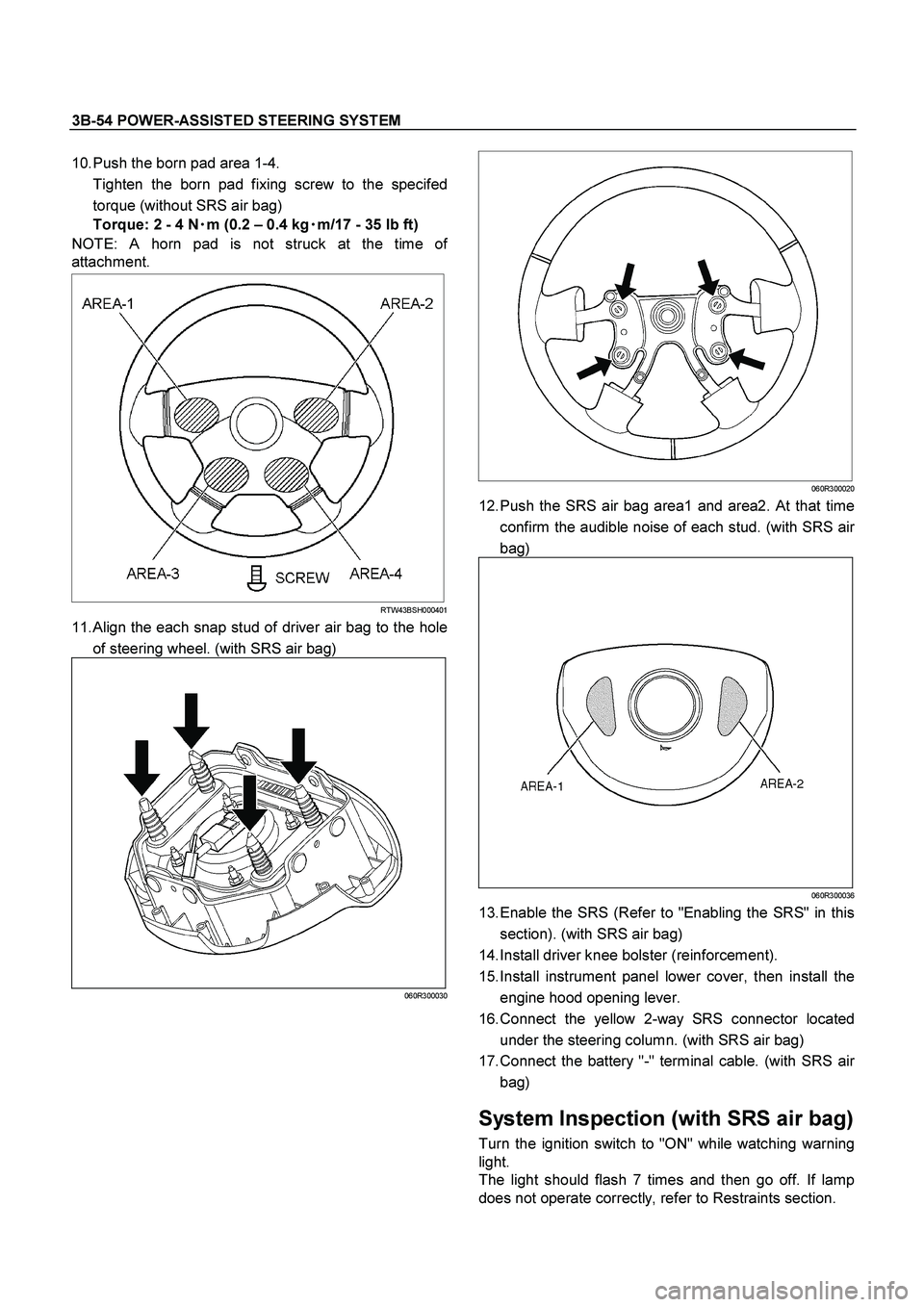
10. Push the born pad area 1-4.
Tighten the born pad fixing screw to the specifed
torque (without SRS air bag)
Torque: 2 - 4 N�
�� �m (0.2 – 0.4 kg�
�� �m/17 - 35 lb ft)
NOTE: A horn pad is not struck at the time o
f
attachment.
RTW43BSH000401
11. Align the each snap stud of driver air bag to the hole
of steering wheel. (with SRS air bag)
060R300030
060R300020
12. Push the SRS air bag area1 and area2. At that time
confirm the audible noise of each stud. (with SRS ai
r
bag)
060R300036
13. Enable the SRS (Refer to "Enabling the SRS" in this
section). (with SRS air bag)
14. Install driver knee bolster (reinforcement).
15. Install instrument panel lower cover, then install the
engine hood opening lever.
16. Connect the yellow 2-way SRS connector located
under the steering column. (with SRS air bag)
17. Connect the battery "-" terminal cable. (with SRS ai
r
bag)
System Inspection (with SRS air bag)
Turn the ignition switch to "ON" while watching warning
light.
The light should flash 7 times and then go off. If lamp
does not operate correctly, refer to Restraints section.
Page 3485 of 4264
POWER-ASSISTED STEERING SYSTEM 3B-55
Steering Column
Steering Column and Associated Parts
This illustration is based on the RHD model.
RTW43BLF000201
Legend
(1) Inflator Module or Horn Pad
(2) Steering Wheel
(3) Steering Column Cover
(4) Combination Switch and SRS Coil Assembly
(5) Steering Column Assembly
(6) Second Steering Shaft
(7) Lower Second Steering Shaft
(8) Instrument Panel Lower Cover
(9) Driver Knee Bolster (reinforcement)
Removal
1. Turn the steering wheel so that the vehicle's wheels
are pointing straight ahead.
2. Turn the ignition switch to "LOCK".
3. Disconnect the battery "-" terminal cable, and wait at
least 5 minutes. (with SRS air bag)
4. Disconnect the yellow 2-way SRS connector located
under the steering column. (with SRS air bag)
Page 3488 of 4264
3B-58 POWER-ASSISTED STEERING SYSTEM
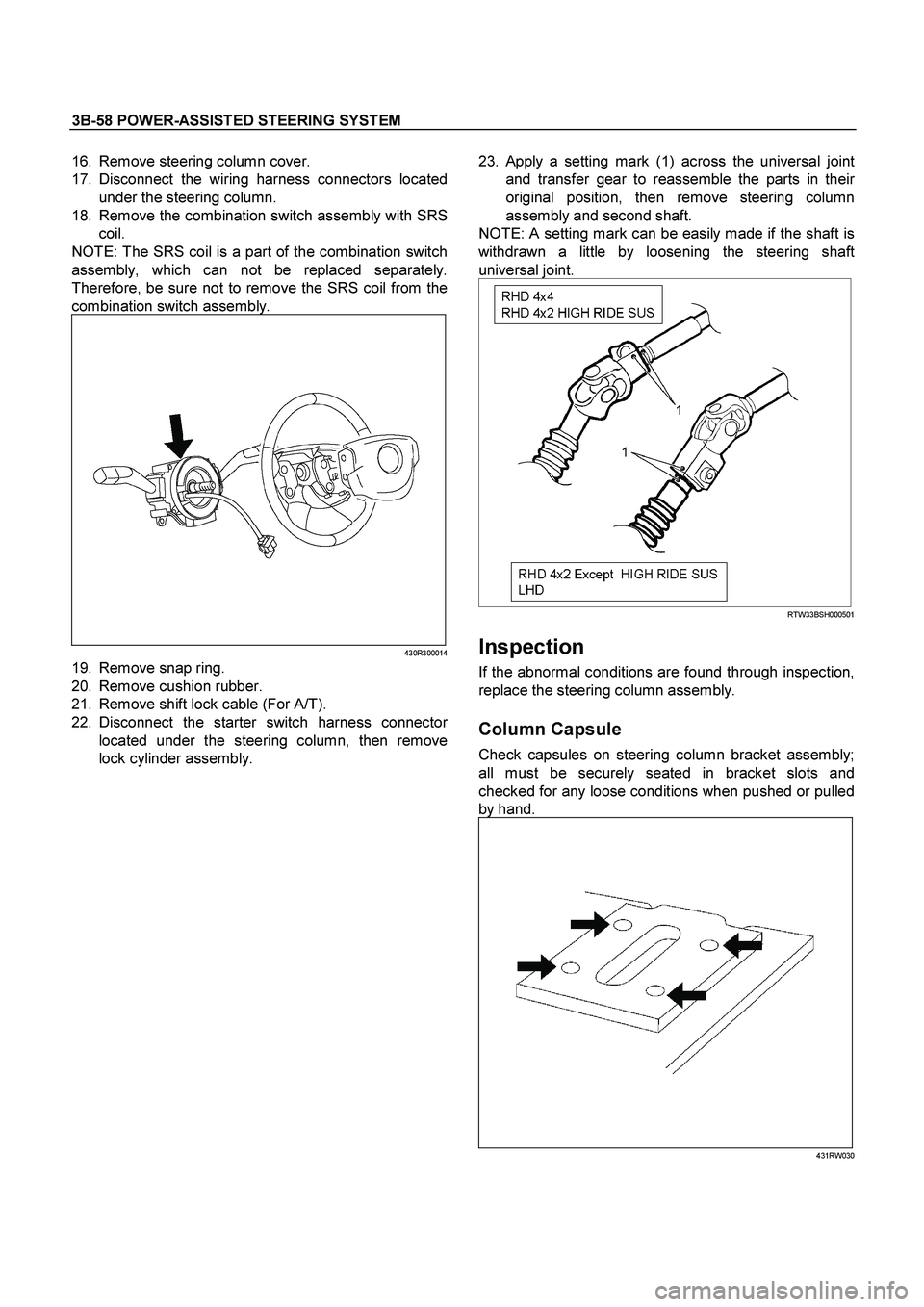
16. Remove steering column cover.
17. Disconnect the wiring harness connectors located
under the steering column.
18. Remove the combination switch assembly with SRS
coil.
NOTE: The SRS coil is a part of the combination switch
assembly, which can not be replaced separately.
Therefore, be sure not to remove the SRS coil from the
combination switch assembly.
430R300014
19. Remove snap ring.
20. Remove cushion rubber.
21. Remove shift lock cable (For A/T).
22. Disconnect the starter switch harness connecto
r
located under the steering column, then remove
lock cylinder assembly.
23.
Apply a setting mark (1) across the universal joint
and transfer gear to reassemble the parts in thei
r
original position, then remove steering column
assembly and second shaft.
NOTE: A setting mark can be easily made if the shaft is
withdrawn a little by loosening the steering shaft
universal joint.
RTW33BSH000501
Inspection
If the abnormal conditions are found through inspection,
replace the steering column assembly.
Column Capsule
Check capsules on steering column bracket assembly;
all must be securely seated in bracket slots and
checked for any loose conditions when pushed or pulled
by hand.
431RW030
Page 3489 of 4264
POWER-ASSISTED STEERING SYSTEM 3B-59
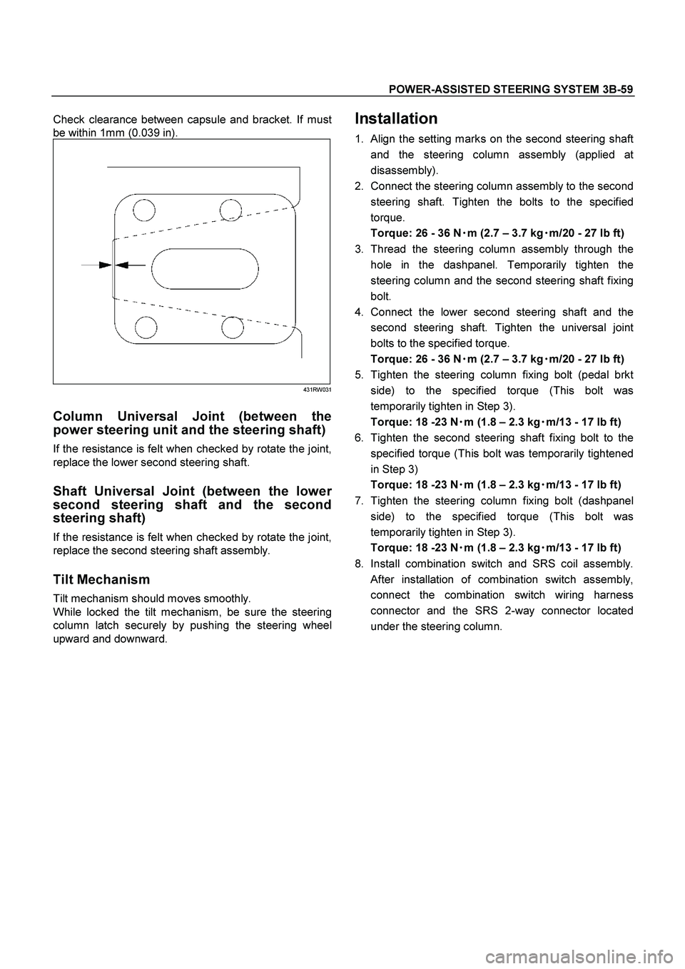
Check clearance between capsule and bracket. If must
be within 1mm (0.039 in).
431RW031
Column Universal Joint (between the
power steering unit and the steering shaft)
If the resistance is felt when checked by rotate the joint,
replace the lower second steering shaft.
Shaft Universal Joint (between the lower
second steering shaft and the second
steering shaft)
If the resistance is felt when checked by rotate the joint,
replace the second steering shaft assembly.
Tilt Mechanism
Tilt mechanism should moves smoothly.
While locked the tilt mechanism, be sure the steering
column latch securely by pushing the steering wheel
upward and downward.
Installation
1. Align the setting marks on the second steering shaft
and the steering column assembly (applied at
disassembly).
2. Connect the steering column assembly to the second
steering shaft. Tighten the bolts to the specified
torque.
Torque: 26 - 36 N�
�� �m (2.7 – 3.7 kg�
�� �m/20 - 27 lb ft)
3. Thread the steering column assembly through the
hole in the dashpanel. Temporarily tighten the
steering column and the second steering shaft fixing
bolt.
4. Connect the lower second steering shaft and the
second steering shaft. Tighten the universal joint
bolts to the specified torque.
Torque: 26 - 36 N�
�� �m (2.7 – 3.7 kg�
�� �m/20 - 27 lb ft)
5. Tighten the steering column fixing bolt (pedal brkt
side) to the specified torque (This bolt was
temporarily tighten in Step 3).
Torque: 18 -23 N�
�� �m (1.8 – 2.3 kg�
�� �m/13 - 17 lb ft)
6. Tighten the second steering shaft fixing bolt to the
specified torque (This bolt was temporarily tightened
in Step 3)
Torque: 18 -23 N�
�� �m (1.8 – 2.3 kg�
�� �m/13 - 17 lb ft)
7. Tighten the steering column fixing bolt (dashpanel
side) to the specified torque (This bolt was
temporarily tighten in Step 3).
Torque: 18 -23 N�
�� �m (1.8 – 2.3 kg�
�� �m/13 - 17 lb ft)
8. Install combination switch and SRS coil assembly.
After installation of combination switch assembly,
connect the combination switch wiring harness
connector and the SRS 2-way connector located
under the steering column.