Page 3458 of 4264

3B-28 POWER-ASSISTED STEERING SYSTEM
Inspection and Repair
Make all necessary adjustments, repairs, and part
replacements if wear, damage, or other problems are
discovered during inspection.
Rotor
442RS002
Check that the groove in the vane is free from excessive
wear and that the vane slides smoothly. When par
t
replacement becomes necessary, the pump cartridge
should be replaced as a subassembly.
Vane
442RS003
Sliding faces of the vane should be free from wear.
(Particularly the curved face at the tip that contact with
the cam should be free from wear and distortion). When
part replacement becomes necessary, the pump
cartridge should be replaced as a subassembly.
Cam
The inner face of the arm should have a uniform contact
pattern without a sign of step wear. When part
replacement becomes necessary, the pump cartridge
should be replaced as a subassembly.
Side Plate
The sliding faces of parts must be free from step wear
(more than 0.01 mm), which can be felt by the finge
r
nail.
The parts with minor scores may be reused after lapping
the face.
Relief Valve
The sliding face of the valve must be free from burrs
and damage. The parts with minor scores may be
reused after smoothing with emery cloth (#800 or finer).
Shaft
Oil seal sliding faces must be free from a step wear
which can be felt by the finger nail. Bushing fitting face
must be free from damage and wear.
O-ring, Oil Seal, Snap Ring
Be sure to discard used parts, and always use new
parts for installation. Prior to installation, lubricate all
seals and rings with power steering fluid.
Pressure Switch
Check the switch operation as follows:
With engine idling and A/C on, turn the steering wheel
fully to the left; compressor should interrupt and engine
idle speed will increase. Shut off A/C and again turn
steering fully to the left; engine idle will increase. I
f
system fails to function properly, disconnect connecto
r
at the pressure switch and repeat system check while
testing continuity across disconnected SW connector.
Reassembly
1. Install oil seal to front housing. Be sure to discard
used oil seal, and always use new parts fo
r
installation.
CAUTION: When installing the oil seal, be careful
not to damage the oil seal contacting surface of the
housing.
2. Install shaft assembly.
Page 3459 of 4264

POWER-ASSISTED STEERING SYSTEM 3B-29
3. Install the vanes to roter with curved face in contact
with the inner wall of cam.
442RS005
4. Install rotor and vanes to cam.
5. Install pin to front housing.
6. Install two new O-rings to front housing. Be sure to
discard used O-ring.
7. Install side plate.
CAUTION: When installing side plate, be careful not
to damage its inner surface. Damaged side plate
may cause poor pump performance, pump seizure
or oil leakage.
8. Install pump cartridge assembly to front housing.
9. Install snap ring to shaft end.
10. Install rear housing with a new O-ring. Be sure to
discard used O-ring. Then install bolt and tighten i
t
to specified torque.
Torque: 22-26 N�
�� �m (2.2-2.7 kg�
�� �m/16-20 lb ft)
11. Install suction pipe with a new O-ring. Be sure to
discard used O-ring. Then install bolt and tighten i
t
to specified torque.
Torque: 7.8-12 N�
�� �m (0.8-1.2 kg�
�� �m/6-9 lb ft)
12. Install relief valve and spring.
13. Install connector with a new O-ring. Be sure to
discard used O-ring. Tighten the connector to
specified torque.
Torque: 49-69 N�
�� �m (5.0-7.0 kg�
�� �m/36-51 lb ft)
14. Install pressure switch assembly and tighten it to
specified torque.
Torque: 15-20 N�
�� �m (1.5-2.0 kg�
�� �m/11-14 lb ft)
Page 3463 of 4264

POWER-ASSISTED STEERING SYSTEM 3B-33
Removal
1. Turn the steering wheel so that the vehicle's wheels
are pointing straight ahead.
2. Turn the ignition switch to "LOCK".
3. Disconnect the battery "-" terminal cable, and wait a
t
least 5 minutes. (with SRS air bag)
4. Disconnect the yellow 2-way SRS connector located
under the steering column. (with SRS air bag)
CAUTION: The wheels of the vehicle must be
straight ahead and the steering column in the
"LOCK" position before disconnecting the steering
wheel. Failure to do so will cause the coil assembly
to become uncentered which will cause damage to
the coil assembly. (with SRS air bag)
5. Disable the SRS (Refer to "Disabling the SRS" in
this section). (with SRS air bag)
6. Check the both side hole of the steering cover. (with
SRS air bag)
060R300025
7. Check the position of the pins in a hole. Push the
pin in the direction of an arrow. (with SRS air bag)
060R300032
8. Push the four pins at �
5�
6 mm bar. (with SRS air
bag)
060R300031
9. Cancel the lock four pins. (with SRS air bag)
Page 3466 of 4264
3B-36 POWER-ASSISTED STEERING SYSTEM
3. Align the each snap stud of driver air bag to the hole
of steering wheel. (with SRS air bag)
060R300030
060R300020
4. Push the SRS air bag area1 and area2. At that time
confirm the audible noise of each stud.
060R300036
5. Enable the SRS (Refer to "Enabling the SRS" in this
section). (with SRS air bag)
6. Connect the SRS connector. (with SRS air bag)
7. Connect the battery "-" terminal cable. (with SRS ai
r
bag)
8. Turn the ignition switch to "ON" while watching
warning light and check the light should flash 7 times
and then go off. If lamp does not operate correctly,
refer to Restraints section.
Page 3467 of 4264
POWER-ASSISTED STEERING SYSTEM 3B-37
Steering Wheel
Steering Wheel and Associated Parts
430R300013
Legend
(1) Horn Lead
(2) SRS Connector
(3) Steering Wheel
(4) Steering Wheel Fixing Nut
(5) Inflator Module or Horn Pad
Removal
1. Turn the steering wheel so that the vehicle's wheels
are pointing straight ahead.
2. Turn the ignition switch to "LOCK".
3. Disconnect the battery "-" terminal cable, and wait a
t
least 5 minutes. (with SRS air bag)
4.
Disconnect the yellow 2-way SRS connector located
under the steering column. (with SRS air bag)
CAUTION: The wheels of the vehicle must be
straight ahead and the steering column in the
"LOCK" position before disconnecting the steering
wheel. Failure to do so will cause the coil assembly
to become uncentered which will cause damage to
the coil assembly. (with SRS air bag)
5. Disable the SRS (Refer to "Disabling the SRS" in
this section). (with SRS air bag)
Page 3470 of 4264

3B-40 POWER-ASSISTED STEERING SYSTEM
430RX005-X
14. Remove steering column cover.
15. Disconnect the wiring harness connectors located
under the steering column then remove combination
switch and SRS coil assembly.
Installation
1. Align the setting marks made when removing then
install steering wheel.
Refer to the adjustment method in case a mark is
not attached in this section.
NOTE: Confirm SRS and Horn harness connector is
fixed by the steering wheel.
RTW33BSH000601
CAUTION: Never apply force to the steering wheel in
direction of the shaft by using a hammer or othe
r
impact tools in an attempt to remove the steering
wheel. The steering shaft is designed as an energy
absorbing unit.
2. Tighten the steering wheel fixing nut to the specified
torque.
Torque: 31 - 39 N�
�� �
m (3.2 – 4.0 kg�
�� �
m/23 - 29 lb ft)
3. Support the inflator module and carefully connect the
SRS connector and horn lead. (with SRS air bag)
060R300041
4. Connect the horn leads at center of wheel. (without
SRS air bag)
NOTE: Horn leads is letting a bracket top pass.
(Plastic type steering wheel only)
RTW43BSH000301
Page 3471 of 4264
POWER-ASSISTED STEERING SYSTEM 3B-41
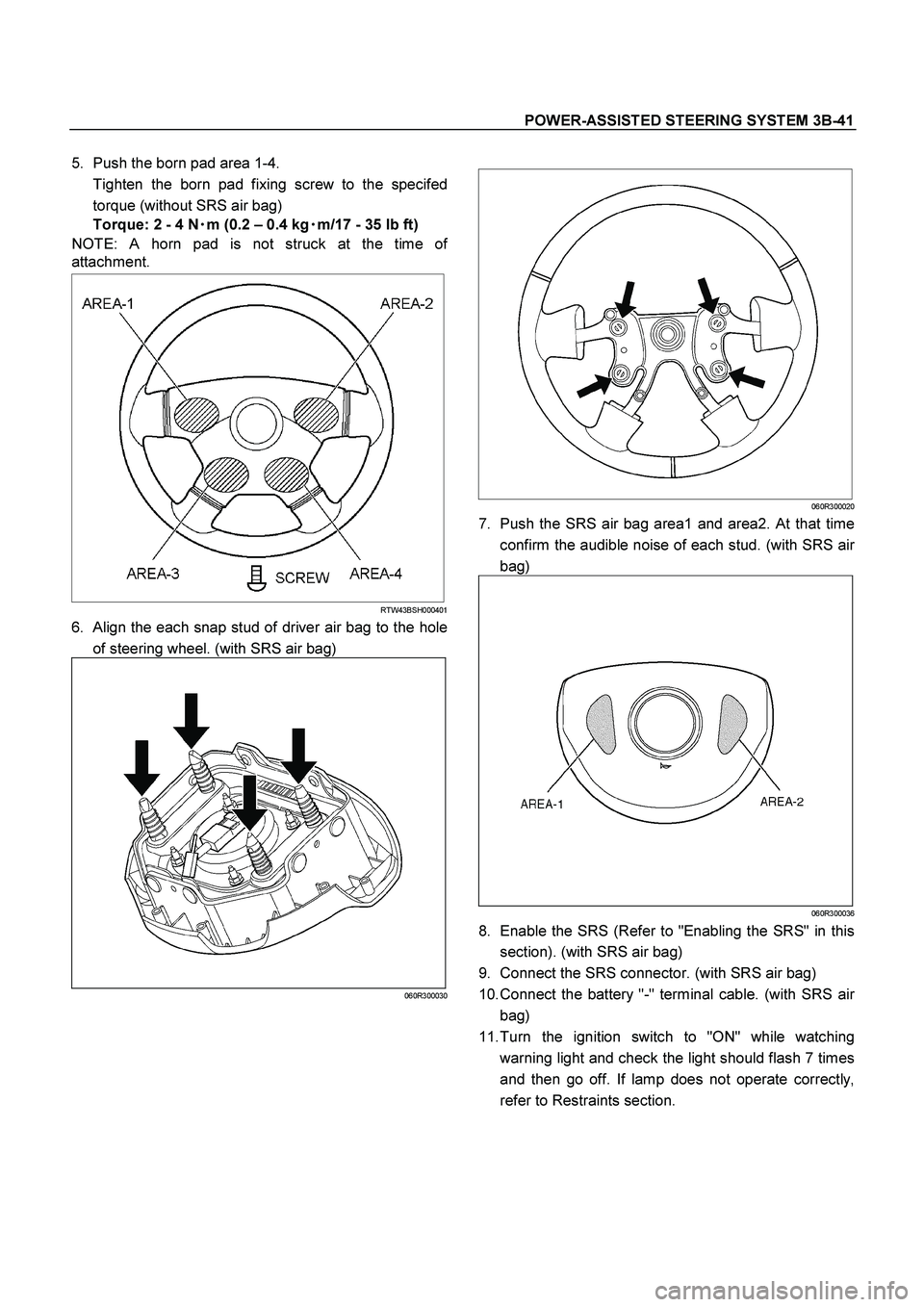
5. Push the born pad area 1-4.
Tighten the born pad fixing screw to the specifed
torque (without SRS air bag)
Torque: 2 - 4 N�
�� �m (0.2 – 0.4 kg�
�� �m/17 - 35 lb ft)
NOTE: A horn pad is not struck at the time o
f
attachment.
RTW43BSH000401
6. Align the each snap stud of driver air bag to the hole
of steering wheel. (with SRS air bag)
060R300030
060R300020
7. Push the SRS air bag area1 and area2. At that time
confirm the audible noise of each stud. (with SRS ai
r
bag)
060R300036
8. Enable the SRS (Refer to "Enabling the SRS" in this
section). (with SRS air bag)
9. Connect the SRS connector. (with SRS air bag)
10. Connect the battery "-" terminal cable. (with SRS ai
r
bag)
11. Turn the ignition switch to "ON" while watching
warning light and check the light should flash 7 times
and then go off. If lamp does not operate correctly,
refer to Restraints section.
Page 3473 of 4264
 Steering Column Cover")
POWER-ASSISTED STEERING SYSTEM 3B-43
Combination Switch
Combination Switch and Associated Parts
This illustration is based on the RHD model.
RTW43BLF000601
Legend
(1) Steering Column Cover
(2) Steering Wheel
(3) Inflator Module or Horn Pad
(4) Combination Switch and SRS Coil Assembly
(5) Instrument Panel Lower Cover
(6) Driver Knee Bolster (reinforcement)
Removal
1. Turn the steering wheel so that the vehicle's wheels
are pointing straight ahead.
2. Turn the ignition switch to "LOCK".
3. Disconnect the battery "-" terminal cable, and wait a
t
least 5 minutes. (with SRS air bag)
4.
Disconnect the yellow 2-way SRS connector located
under the steering column. (with SRS air bag)
CAUTION: The wheels of the vehicle must be
straight ahead and the steering column in the
"LOCK" position before disconnecting the steering
wheel. Failure to do so will cause the coil assembly
to become uncentered which will cause damage to
the coil assembly. (with SRS air bag)
5. Remove the engine hood opening lever, then
remove instrument panel lower cover.
6. Remove the driver knee bolster (reinforcement).

060R300030
060R300020
4. Push the SRS air bag area1 and area")
 Horn Lead
(2) SRS Connector
(3) Steering Wheel
(4) Steering Wheel Fixing Nut")