Page 2366 of 4264
6E-370 3.5L ENGINE DRIVEABILITY AND EMISSIONS
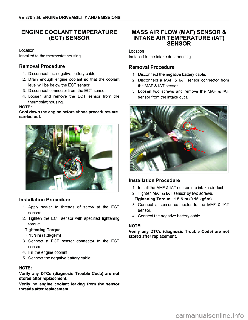
ENGINE COOLANT TEMPERATURE
(ECT) SENSOR
Location
Installed to the thermostat housing.
Removal Procedure
1. Disconnect the negative battery cable.
2. Drain enough engine coolant so that the coolan
t
level will be below the ECT sensor.
3. Disconnect connector from the ECT sensor.
4. Loosen and remove the ECT sensor from the
thermostat housing.
NOTE:
Cool down the engine before above procedures are
carried out.
Installation Procedure
1. Apply sealer to threads of screw at the ECT
sensor.
2. Tighten the ECT sensor with specified tightening
torque.
Tightening Torque
�
�� �13N�
�� �m (1.3kgf�
�� �m)
3. Connect a ECT sensor connector to the ECT
sensor.
4. Fill the engine coolant.
5. Connect the negative battery cable.
NOTE:
Verify any DTCs (diagnosis Trouble Code) are not
stored after replacement.
Verify no engine coolant leaking from the senso
r
threads after replacement.
MASS AIR FLOW (MAF) SENSOR &
INTAKE AIR TEMPERATURE (IAT)
SENSOR
Location
Installed to the intake duct housing.
Removal Procedure
1. Disconnect the negative battery cable.
2. Disconnect a MAF & IAT sensor connector from
the MAF & IAT sensor.
3. Loosen two screws and remove the MAF & IAT
sensor from the intake duct.
Installation Procedure
1. Install the MAF & IAT sensor into intake air duct.
2. Tighten MAF & IAT sensor by two screws.
Tightening Torque : 1.5 N�
�� �m (0.15 kgf�
�� �m)
3. Connect a sensor connector to the MAF & IAT
sensor.
4. Connect the negative battery cable.
NOTE:
Verify any DTCs (diagnosis Trouble Code) are not
stored after replacement.
Page 2367 of 4264
3.5L ENGINE DRIVEABILITY AND EMISSIONS 6E-371
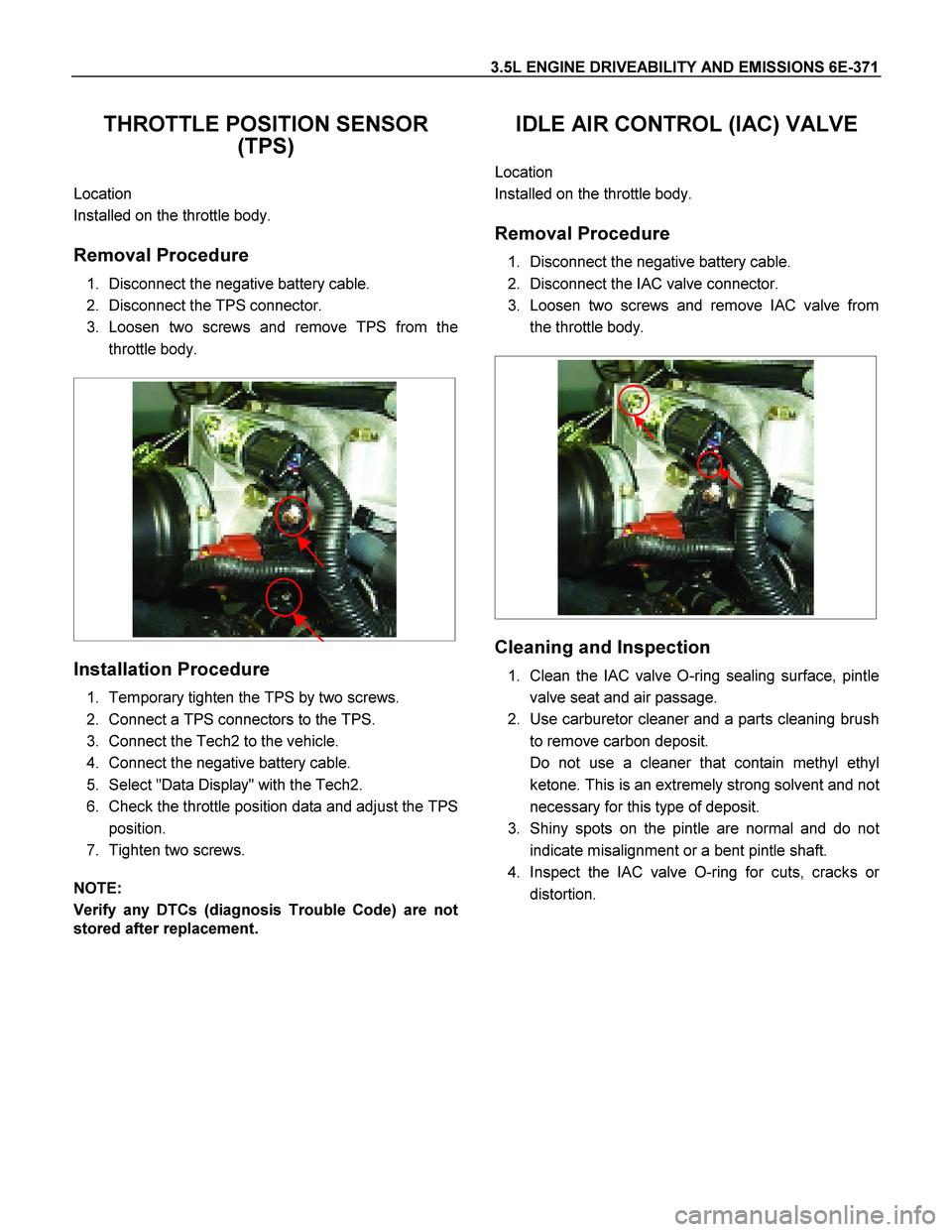
THROTTLE POSITION SENSOR
(TPS)
Location
Installed on the throttle body.
Removal Procedure
1. Disconnect the negative battery cable.
2. Disconnect the TPS connector.
3. Loosen two screws and remove TPS from the
throttle body.
Installation Procedure
1. Temporary tighten the TPS by two screws.
2. Connect a TPS connectors to the TPS.
3. Connect the Tech2 to the vehicle.
4. Connect the negative battery cable.
5. Select "Data Display" with the Tech2.
6. Check the throttle position data and adjust the TPS
position.
7. Tighten two screws.
NOTE:
Verify any DTCs (diagnosis Trouble Code) are not
stored after replacement.
IDLE AIR CONTROL (IAC) VALVE
Location
Installed on the throttle body.
Removal Procedure
1. Disconnect the negative battery cable.
2. Disconnect the IAC valve connector.
3. Loosen two screws and remove IAC valve from
the throttle body.
Cleaning and Inspection
1. Clean the IAC valve O-ring sealing surface, pintle
valve seat and air passage.
2. Use carburetor cleaner and a parts cleaning brush
to remove carbon deposit.
Do not use a cleaner that contain methyl ethyl
ketone. This is an extremely strong solvent and no
t
necessary for this type of deposit.
3. Shiny spots on the pintle are normal and do no
t
indicate misalignment or a bent pintle shaft.
4. Inspect the IAC valve O-ring for cuts, cracks o
r
distortion.
Page 2368 of 4264
6E-372 3.5L ENGINE DRIVEABILITY AND EMISSIONS
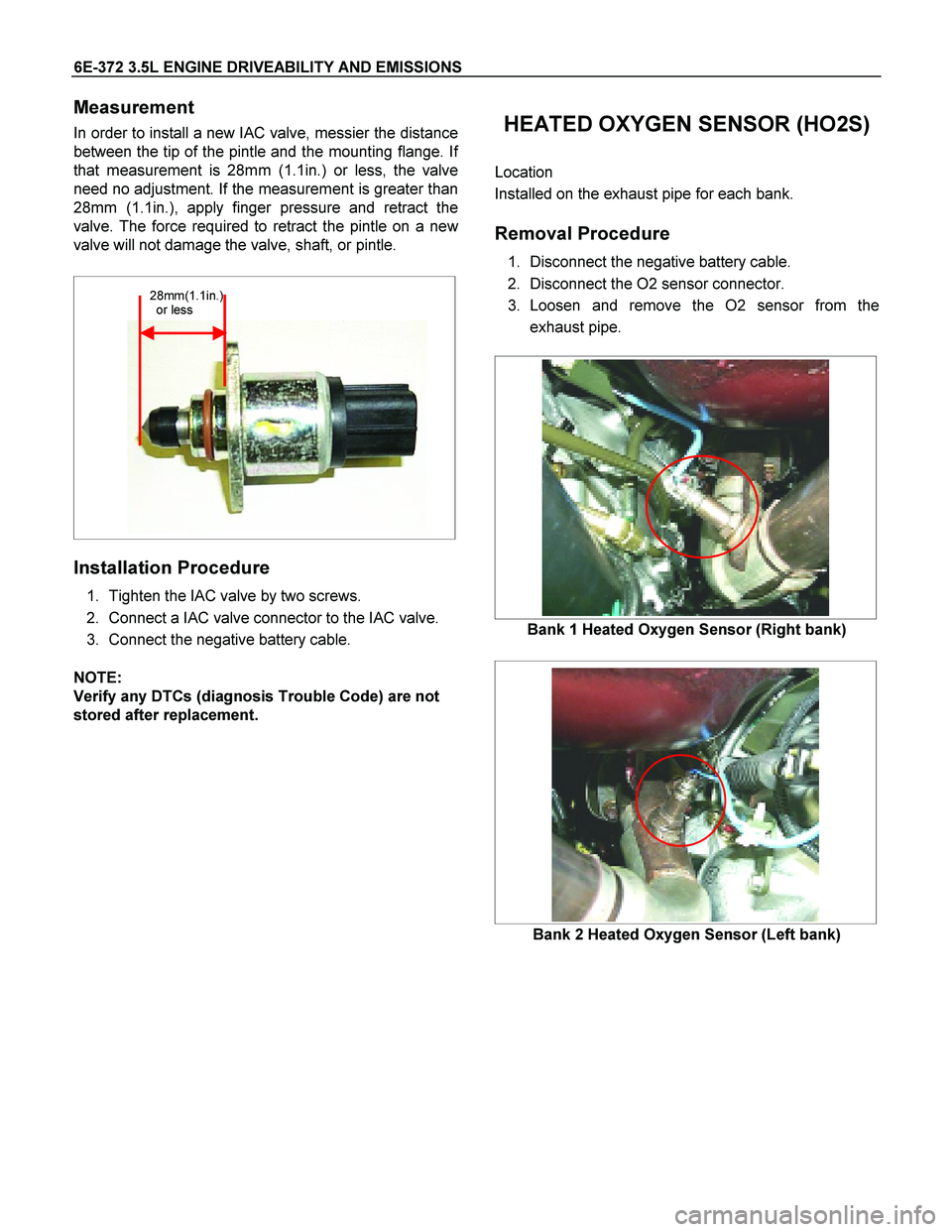
Measurement
In order to install a new IAC valve, messier the distance
between the tip of the pintle and the mounting flange. I
f
that measurement is 28mm (1.1in.) or less, the valve
need no adjustment. If the measurement is greater than
28mm (1.1in.), apply finger pressure and retract the
valve. The force required to retract the pintle on a ne
w
valve will not damage the valve, shaft, or pintle.
28mm(1.1in.)
or less
Installation Procedure
1. Tighten the IAC valve by two screws.
2. Connect a IAC valve connector to the IAC valve.
3. Connect the negative battery cable.
NOTE:
Verify any DTCs (diagnosis Trouble Code) are not
stored after replacement.
HEATED OXYGEN SENSOR (HO2S)
Location
Installed on the exhaust pipe for each bank.
Removal Procedure
1. Disconnect the negative battery cable.
2. Disconnect the O2 sensor connector.
3. Loosen and remove the O2 sensor from the
exhaust pipe.
Bank 1 Heated Oxygen Sensor (Right bank)
Bank 2 Heated Oxygen Sensor (Left bank)
Page 2369 of 4264
3.5L ENGINE DRIVEABILITY AND EMISSIONS 6E-373
Inspection
Inspect the louvered end of the sensor for grease,
dirt, excessive carbon build up or othe
r
contamination.
A special anti-seize compound is used on the O2
sensor threads. This compound consists of glass
breads suspended in a liquid graphite solution.
The graphite burns away with engine heat, but the
glass breads will remain, marking the senso
r
easier to remove.
New or service sensors will already have the
compound applied to the threads. If a sensor is
removed and is to be reinstalled for any reason,
the threads must have anti-seize compound
applied.
Installation Procedure
1. Install the O2 sensor to the exhaust pipe.
Apply anti-seize compound or the equivalent to the
threads of the oxygen sensor, if necessary.
2. Tighten the O2 sensor with specified tightening
torque.
Tightening Torque
�
�� �Bolt: 42N�
�� �m (4.3kgf�
�� �m)
3. Connect a sensor connector to the O2 sensor.
4. Connect the negative battery cable.
NOTE:
Verify any DTCs (diagnosis Trouble Code) are not
stored after replacement.
Verify no exhaust gas leaking from the senso
r
threads after replacement.
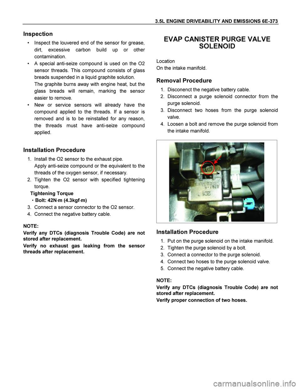
EVAP CANISTER PURGE VALVE
SOLENOID
Location
On the intake manifold.
Removal Procedure
1. Disconenct the negative battery cable.
2. Disconnect a purge solenoid connector from the
purge solenoid.
3. Disconnect two hoses from the purge solenoid
valve.
4. Loosen a bolt and remove the purge solenoid from
the intake manifold.
Installation Procedure
1. Put on the purge solenoid on the intake manifold.
2. Tighten the purge solenoid by a bolt.
3. Connect a connector to the purge solenoid.
4. Connect two hoses to the purge solenoid valve.
5. Connect the negative battery cable.
NOTE:
Verify any DTCs (diagnosis Trouble Code) are not
stored after replacement.
Verify proper connection of two hoses.
Page 2382 of 4264
6F-4 ENGINE EXHAUST (6VE1 3.5L)
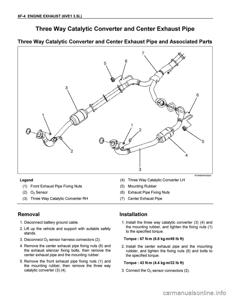
Three Way Catalytic Converter and Center Exhaust Pipe
Three Way Catalytic Converter and Center Exhaust Pipe and Associated Parts
RTW46FMF000201
Legend (4) Three Way Catalytic Converter LH
(1) Front Exhaust Pipe Fixing Nuts (5) Mounting Rubber
(2) O
2 Sensor (6) Exhaust Pipe Fixing Nuts
(3) Three Way Catalytic Converter RH (7) Center Exhaust Pipe
Removal
1. Disconnect battery ground cable.
2. Lift up the vehicle and support with suitable safety
stands.
3. Disconnect O
2 sensor harness connectors (2).
4. Remove the center exhaust pipe fixing nuts (6) and
the exhaust silencer fixing bolts, then remove the
center exhaust pipe and the mounting rubber.
5. Remove the front exhaust pipe fixing nuts (1) and
the mounting rubber, then remove the three way
catalytic converter (3) (4).
Installation
1. Install the three way catalytic converter (3) (4) and
the mounting rubber, and tighten the fixing nuts (1)
to the specified torque.
Torque : 67 N�
�� �m (6.8 kg�
�� �m/49 lb ft)
2. Install the center exhaust pipe and the mounting
rubbler, and tighten the fixing nuts (6) and bolts to
the specified torque.
Torque : 43 N�
�� �m (4.4 kg�
�� �m/32 lb ft)
3. Connect the O
2 sensor connectors (2).
Page 2402 of 4264
6J-2 INDUCTION (6VE1 3.5L)
Air Cleaner
Removal
1. Remove positive ventilation hose connector.
2. Remove MAF and IAT sensor.
3. Remove air cleaner duct assembly.
4. Remove air cleaner housing.
P1010024
Inspection
Check the air cleaner filter for damage or dust clogging.
Replace if it is damaged, or clean if it is clogged.
Cleaning Method
Tap the air cleaner filter gently so as not to damage the
paper filter, or clean the element by blowing with
compressed air of about 490 kPa (71 psi) from the
clean side if it is extremely dirty.
130RW002
Installation
1. Install air cleaner housing.
NOTE: The air cleaner filter is not damaged with the
edge to an air cleaner housing.
RTW46JSH000101
2. Attach the mass air cleaner duct cover to the body
completely, then clamp it with the clip.
3. Install MAF and IAT sensor.
4. Install positive crankcase ventilation hose connector.
P1010024
Page 2410 of 4264
6-4 ENGINE DIAGNOSIS (C24SE)
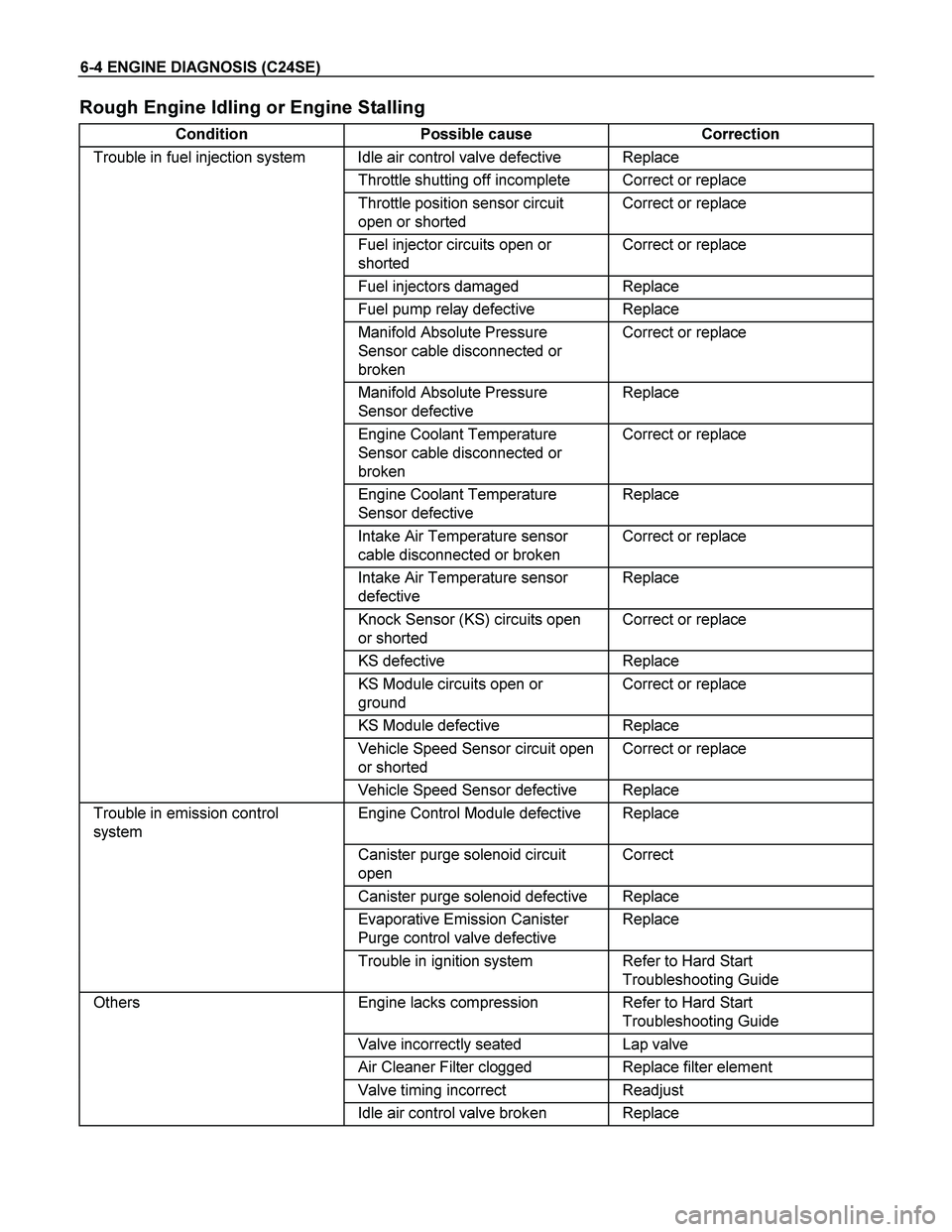
Rough Engine Idling or Engine Stalling
Condition Possible cause Correction
Trouble in fuel injection system Idle air control valve defective Replace
Throttle shutting off incomplete Correct or replace
Throttle position sensor circuit
open or shorted Correct or replace
Fuel injector circuits open or
shorted Correct or replace
Fuel injectors damaged Replace
Fuel pump relay defective Replace
Manifold Absolute Pressure
Sensor cable disconnected or
broken Correct or replace
Manifold Absolute Pressure
Sensor defective Replace
Engine Coolant Temperature
Sensor cable disconnected or
broken Correct or replace
Engine Coolant Temperature
Sensor defective Replace
Intake Air Temperature sensor
cable disconnected or broken Correct or replace
Intake Air Temperature sensor
defective Replace
Knock Sensor (KS) circuits open
or shorted Correct or replace
KS defective Replace
KS Module circuits open or
ground Correct or replace
KS Module defective Replace
Vehicle Speed Sensor circuit open
or shorted Correct or replace
Vehicle Speed Sensor defective Replace
Trouble in emission control
system Engine Control Module defective Replace
Canister purge solenoid circuit
open Correct
Canister purge solenoid defective Replace
Evaporative Emission Canister
Purge control valve defective Replace
Trouble in ignition system Refer to Hard Start
Troubleshooting Guide
Others Engine lacks compression Refer to Hard Start
Troubleshooting Guide
Valve incorrectly seated Lap valve
Air Cleaner Filter clogged Replace filter element
Valve timing incorrect Readjust
Idle air control valve broken Replace
Page 2411 of 4264
ENGINE DIAGNOSIS (C24SE) 6-5
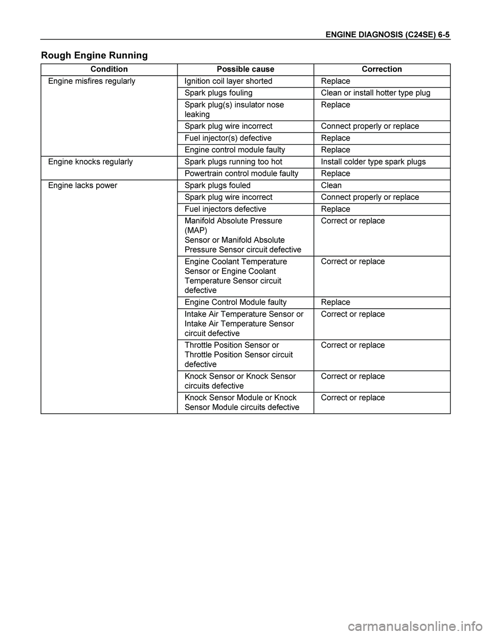
Rough Engine Running
Condition Possible cause Correction
Engine misfires regularly Ignition coil layer shorted Replace
Spark plugs fouling Clean or install hotter type plug
Spark plug(s) insulator nose
leaking Replace
Spark plug wire incorrect Connect properly or replace
Fuel injector(s) defective Replace
Engine control module faulty Replace
Engine knocks regularly Spark plugs running too hot Install colder type spark plugs
Powertrain control module faulty Replace
Engine lacks power Spark plugs fouled Clean
Spark plug wire incorrect Connect properly or replace
Fuel injectors defective Replace
Manifold Absolute Pressure
(MAP)
Sensor or Manifold Absolute
Pressure Sensor circuit defective Correct or replace
Engine Coolant Temperature
Sensor or Engine Coolant
Temperature Sensor circuit
defective Correct or replace
Engine Control Module faulty Replace
Intake Air Temperature Sensor or
Intake Air Temperature Sensor
circuit defective Correct or replace
Throttle Position Sensor or
Throttle Position Sensor circuit
defective Correct or replace
Knock Sensor or Knock Sensor
circuits defective Correct or replace
Knock Sensor Module or Knock
Sensor Module circuits defective Correct or replace